
DISCLAIMER
The draft recommendations contained herein were preliminary drafts submitted for discussion purposes only and do not constitute final determinations. They have been subject to modification, substitution, or rejection and may not reflect the adopted positions of IFATCA. For the most current version of all official policies, including the identification of any documents that have been superseded or amended, please refer to the IFATCA Technical and Professional Manual (TPM).
55TH ANNUAL CONFERENCE, Las Vegas, USA, 14-18 March 2016WP No. 158Airspace Design and Procedures Controller InvolvementPresented by TOC |
Summary
Efforts to redesign airspace have ramped up in recent years as ANSPs and airlines push for more advanced RNAV and RNP procedures to improve the efficiency of airspace and aircraft. Major redesign efforts have already been implemented and a tremendous amount of experience has been acquired as a result. This paper first reviews ICAO guidelines for controller involvement, then reviews recent projects, documenting many important lessons learned to benefit those who will embark on such projects in the future.
Introduction
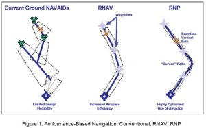
1.1 Traditional airspace design and procedures in the vicinity of major airports have become obsolete. Replacing them are airspace and procedures made possible by more precise navigation systems that use Area Navigation (RNAV) and vertical guidance capabilities. Highly customized approach and departure trajectories are now possible within assigned vertical windows. This enables more efficient use of the airspace while simultaneously providing pilots with more flexibility in selecting a trajectory. Figure 1 illustrates the concept. Note that everyone wants shorter lateral tracks, but individual carriers and even departments within each carrier may differ on the optimum vertical profile.
(“Environmental Assessment for Atlanta Optimization of Airspace and Procedures in the Metroplex”, March 2014, FAA)
1.2 New airspace and procedures require participating aircraft to meet performance standards. These onboard navigation capabilities, including the ability of aircraft to fly along a precise flight path with improved accuracy and within a vertical profile, are known as Required Navigational Performance (RNP). NextGen and SESAR solutions depend on RNAV and RNP equipage and implementation.
1.3 RNP can reduce the cost of inefficiencies such as multiple step-down arrival procedures and non-precision approaches, and also reduce the occurrence of missed approaches. RNP and other procedures can increase airspace capacity by shortening the arrival and departure paths (“Understanding Required Navigation Performance (RNP) and Area Navigation (RNAV) Operations”, Universal Avionics Systems Corporation, White Paper, October 2013). Note that these benefits tend to be greatest at airports with simpler runway configurations and high volume.
1.4 By redesigning airspace using RNP and continuous climb/descent procedures, airspace designers can not only improve the efficiency of the airspace and reduce frequency congestion, but can provide aircraft with descent profiles that save fuel. As a result, there is global demand for these procedures. But the role of the system users, pilots and controllers, in the redesign process is critical. An Asian ANSP recently deployed 200 PBN procedures, none of which are being used.
1.5 In 2008, the Performance-based Navigation (PBN) Concept was introduced through publication of the ICAO PBN Manual (Doc 9613) in 2008. The PBN Concept is geared to respond to airspace requirements and, according to Eurocontrol, the PBN concept replaced the RNP concept (“Airspace Concept Handbook for the Implementation of Performance Based Navigation (PBN)”, Eurocontrol, April 2010). Implementation of PBN is the global aviation community’s highest Air Navigation priority as PBN is an enabler of continuous climb and descent, according to the ICAO iKIT slide in Figure 2.

1.6 In September 2009, the RTCA Task Force 5 issued a report including recommendations to provide a systematic, integrated and expedited approach to implementing PBN procedures and associated airspace changes. The process focuses on geographic areas, rather than single airports and in the US is known as “Metroplex”. It covers planning to post-implementation and suggests a three-year time frame.
1.7 In 2013, ICAO Doc 9992, Manual on the use of Performance-based Navigation (PBN) in Airspace Design was published.
1.8 This paper examines various PBN airspace projects in light of the ICAO standards. It evaluates the success of these projects, particularly with respect to the involvement of controllers in the process, but also in terms of stated objectives and goals.
1.9 This paper also seeks to document some of the issues designers have had thus far and thereby help others avoid making the same mistakes. The experience gained in major airspace redesign projects is not always documented so as to be available to other designers around the globe.
Discussion
Controller involvement
2.1 Understanding the role of the controller in airspace redesign starts with understanding the redesign process.
2.2 ICAO Doc 9992, Manual of the Use of Performance-based Navigation in Airspace Design
2.2.1 ICAO speaks very clearly and directly to the issue of successful implementation of airspace redesign in Doc 9992 as follows:
| 2.1.2 Airspace redesign is usually initiated by an event which triggers an operational requirement. Such events are often categorized by one or more strategic objectives such as safety, capacity, flight efficiency, environmental mitigation or access. While some of these strategic objectives may be explicit in the proposed airspace change, the remainder will remain implicit objectives insofar as they should not normally be adversely affected by the proposed change. There are often conflicts between these objectives, and they must be prioritized, ensuring at all times that the maintenance of safety remains paramount. 2.1.3 There are two prerequisites to a successful airspace concept development:
a) comprehensive preparation — planning must take account of all aspects and must address all related stakeholder concerns; and b) iteration — airspace development is not a linear process — it can only result in a sound product through a series of reviews, validations and subsequent refinements. Success can only be achieved through comprehensive planning which establishes the scope and objectives of the airspace concept, based on the operational requirements. |
2.2.2 ICAO Doc 9992 also states that, “The requirements driving an airspace redesign should be clearly stated in a written document detailing strategic objectives so that subsequent work has a clear direction.” The lack of such documentation immediately suggests the process went astray from the beginning.
2.2.3 Controller involvement is specifically identified in section 2.2.2. Note that air traffic controllers familiar with local operations are the first group identified in the list (yellow highlighting for this paper, 2.2.2.2 a).
| 2.2.2 Activity 2: Create the airspace design team 2.2.2.1 In order to respond to the operational requirement identified in Activity 1, an airspace concept must be developed, validated and implemented. The airspace concept must address all of the requirements and cannot be developed by a single individual working in isolation. Airspace concepts, from inception to implementation, are the product of an integrated team working together — the airspace design team.
2.2.2.2 The airspace design team should be led by an ATM specialist with strong project management skills and an in-depth operational knowledge of the specific airspace under review. This ATM specialist would work in collaboration with: a) air traffic controllers who are also familiar with operations in the airspace; b) ATM and CNS system specialists who are familiar with the existing, and planned, CNS/ATM systems; c) technical pilots from operators who use the airspace; d) airspace designers and instrument flight procedure designers; e) other airspace users (such as military, GA); f) airport and environmental managers; and g) experts from additional disciplines as deemed necessary, e.g. economists or data house specialists. |
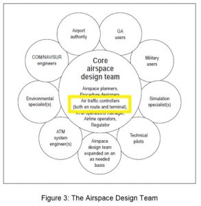
2.2.4 The airspace design team is visualized by ICAO in Figure 4. Note the presence of air traffic controllers, both en route (area) and terminal, in the core portion of the team.
2.2.5 Another section speaks to the importance of understanding the local traffic.
| 2.2.6.5.1 The success of an airspace concept can stand or fall on its traffic assumptions. Various models may be used to determine air traffic forecasts, and although the existing ATC knowledge of the air traffic movements can help considerably, the proposed traffic sample for 20XX must be thoroughly analysed, taking into account projections from all affected stakeholders. Invariably, certain characteristics will be identified in the traffic sample, e.g. seasonal, weekly or daily variations in demand, changes to peak hours, and the relationship between arrival and departure flows must all be taken into account in the airspace concept… |
Only current air traffic controllers possess intimate knowledge of the traffic flows to insure the airspace concept is valid.
2.2.6 Operational controllers are again identified as central to the process in section 2.3.1.3.
| 2.3.1.3 The procedure designer must participate in the initial conceptual design led by the operational controllers, acting as a facilitator during this process and providing guidance on the proposed route placement from both an obstacle/airspace clearance and an aircraft performance perspective. |
2.2.7 Real-time simulation (RTS) is considered by Doc 9992 as the “closest simulation method to the live ATC trials that can be used to assess and validate simulation objectives.” RTS is critical to implementation as described below.
| 2.4.2.11.1 RTS is used in the later stages of the validation of a proposed airspace design and may also be used as a way of demonstrating that both the safety objectives and operational objectives have been met. RTS is often used as a final check and preparatory step towards implementation. This method is used mainly because it provides live feedback from the operational air traffic controllers and for its potential for a high degree of realism. RTS also allows air traffic controllers to become familiar with proposed changes. |
2.2.8 Doc 9992 also describes the circumstances around which the final, go/no-go decision is made. It does not define explicitly the decision-maker, but the input from the airspace design team would weigh heavily. The design group must have a well-defined process with milestones for each phase.
| 2.5.1.2 The decision to go ahead with implementation will be based on certain deciding factors as follows:
a) the ATS route/procedure design meets air traffic and flight operations’ needs; b) the safety and navigation performance requirements have been satisfied; c) the changes to flight plan processing, automation, AIP publications needed to support the implementation have been completed; and d) the pilot and controller training requirements have been met. |
2.2.9 If new interfaces and displays are required in the control room to support the new airspace design, the acceptance by controllers of this equipment is vital to the success of the project. It is also vital that controllers accept the mixed mode environment that often results from PBN-related airspace changes.
2.3 Eurocontrol’s Airspace Concept Handbook for the Implementation of Performance Based Navigation (PBN)
2.3.1 This document is an excellent resource for ANSPs and airspace designers intending to implement PBN procedures. It includes a detailed 15 step process which it calls “Activities for Airspace Concept development”. These activities are broken down into four general categories, Planning, Design, Validation and Implementation.
2.3.2 Activity 1 is drafting the operational requirements, and Activity 2 is building the design team. The document specifies a team built as above in the ICAO graphic (Figure 3). Air traffic controllers, both en route and approach, are again core members along with designers, planners and an ATM manager.
As the document states, “Commonly, this team is led by an ATM specialist with an in depth operational knowledge of the specific airspace under review. This specialist will need to be supported by Air Traffic Controllers familiar with the airspace in question, ATM and CNS System specialists and Technical pilots from lead carriers operating in the airspace.”
2.3.3 Activity 6 addresses assumptions about equipage. No project can move forward without knowledge of the capabilities of the participating aircraft in communications, navigation and surveillance, not just at present but also as expected in the future. Aircraft and pilots must be able and willing to fly the new procedures or the project is worthless. This does happen as mentioned in 1.4.
2.3.4 Activity 10 is “Selecting an ICAO Navigation Specification”. With a realistic view of current and future equipage from Activity 6, designers can move ahead and settle on the Airspace Classification, and what ICAO Specification will be required.
2.3.5 Controllers may be expected to accommodate aircraft that do not meet the Navigation Specification and/or work traffic in a mixed mode environment. If so, this is a decision that should not just involve controllers but be made by controllers as the ability to handle mixed mode traffic can be very problematic.
Recent Redesign Projects and Experiences
2.4 Denver Metroplex
2.4.1 In the summer of 2014, work began to redesign airspace around Denver, Colorado in the United States. This project is known as Denver Metroplex.
2.4.2 The primary goal of the Denver Metroplex Study Team (MST) was to create procedures utilizing RNAV everywhere and Required Navigation Performance (RNP) where beneficial. The use of PBN procedures would allow efficiency gains through optimized profile climbs/descents and enhanced lateral paths not reliant on ground based navigation, while allowing predictability and repeatability, reducing ATC task complexity, and frequency congestion.
The proposed departure procedures attempted to provide for unrestricted climbs while providing procedural segregation from other Standard Instrument Departures (SIDs) and Standard Terminal Arrival Routes (STARs). It was fully expected that ATC would continue to tactically enable shorter routings and remove climb restrictions. Additionally, the use of transitional separation between terminal and en route facilities would increase airspace efficiency.
2.4.3 The project used a five step analysis process (“Denver Metroplex Study Team Final Report”, November 2014, FAA Denver Metroplex Study Team):
| 1. Collaboratively identified and characterized existing issues:
a. Reviewed current operations b. Solicited input to obtain an understanding of the broad view of operational challenges in the Metroplex 2. Proposed notional procedure designs that address the issues and will optimize the operation: a. Used an Integrated Airspace and PBN Toolbox b. Obtained technical input from operational stakeholders c. Explored potential solutions to the identified issues 3. Quantitatively and qualitatively identified the expected benefits of the notional designs: a. Assessed the Rough Order of Magnitude (ROM) impacts of notional designs b. Used objective and quantitative assessments as required 4. Identified considerations and risks associated with the proposed changes: a. Described high-level considerations (e.g., if additional feasibility assessments are needed) b. Assessed risks (e.g., if waivers may be needed) 5. Documented results |
2.4.4 Airspace and procedure changes were evaluated with respect to the following considerations and how they would be affected:
- Impact on ATC task complexity
- Effective traffic flow management
- Ability to laterally and/or vertically segregate flows
- Impact of flow segregation to/from adjacent facilities
- Ability to enhance safety
- Improved connectivity to en route structure
- Reduction in pilot-controller transmissions minimizing frequency congestion
- Improved track predictability and repeatability
- More efficient fuel planning
- Reduced reliance on ground-based navigational aids (NAVAID)
- Increased system efficiencies
2.4.5 The project evaluated benefits according to metrics including track lengths, flight times, time in level flight, and fuel burn. The study team – including current, local air traffic controllers – was data centric and not biased by “the way we have always done it.” They looked at the historical track data and how to improve tracks flown from a quantitative standpoint for pilots and carriers, including fuel burn, CO2 emissions, track miles, and optimum profile descents. They also considered qualitative improvements for controllers such as making the traffic less complex through de-confliction and reducing frequency congestion.
2.4.6 One methodology the Denver Metroplex used was the identification of commonly used shortcuts. This is comparable to a method used in office complex landscaping. Rather than install sidewalks and paths at the completion of construction, designers wait for a period of time to see where the residents of the complex walk. Wherever pedestrian traffic wears down the grass into a path, sidewalks are installed. By doing this, the residents are less inclined to walk off the sidewalks and the grass and landscaping are generally untouched.
2.4.7 In the same way, airspace designers review the paths airplanes typically take and then use that knowledge in designing procedures. Pilots will ask for the shortcuts they want, and controllers will approve those that help move the traffic. The goal of this method is a natural and efficient traffic flow.
2.4.8 Regarding qualitative data, the Denver Metroplex report states:
| An example of qualitative assessment is task complexity, which can be lessened through the application of structured PBN procedures versus the use of radar vectors, but quantifying that impact is difficult. Reduced communications between pilot and controller, as well as reduced potential for operational errors are examples of metrics associated with controller task complexity that cannot be quantified. |
The inability to measure task complexity and the effect of reduced communications and reduced error potential require subjective feedback from controllers.
2.4.9 Regarding quantifiable data, the report states:
| The Metroplex Study Team (MST) identified changes in track lengths, flight times, time in level flight, and fuel burn. Potential benefits were measured by comparing current flights to the MST proposed procedures using a Markov Chain Monte Carlo method to approximate aircraft behavior based on distributions from historic radar tracks. |
Compilation and analysis of these data provide designers with measurable results.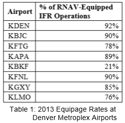
2.4.10 An important aspect of any new procedure is equipage. Non-equipped aircraft will require additional procedures that will consume airspace and can put an inordinate burden on controllers during busy periods. The Denver Metroplex report includes survey data of the user community as shown in Table 1.
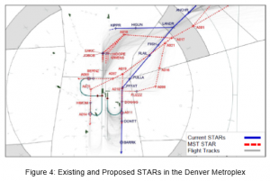
2.4.11 The result of the project was to optimize vertical profiles, shorten lateral paths, segregate route, remove unused en route transitions, reduce the number of STARs, and propose flow dependent transitions. Arrival procedures for satellites in the area were created. Some were procedurally segregated from DEN SIDs and STARs. Some of the new STARs are shown in Figure 4.
2.4.12 The estimated benefits were as shown in Table 2.

2.5 Houston, Texas, USA Metroplex
2.5.1 On May 29, 2014, the Houston Metroplex project implemented 60 new or modified arrival and departure procedures. A MITRE study predicted a fuel savings among all carriers of10 million USD annually because of more efficient routes and trajectories (“Houston Metroplex Post-Implementation Analysis”, January 2015, MITRE).
2.5.2 The project featured three major themes: o Procedures optimized to reduce the path distance and to provide for efficient vertical profiles. o Operational incentives to use the procedures. o Use of time-based flow management to insure appropriate spacing under changing wind and traffic conditions. If intervention is required during continuous descent procedures then the benefit of the procedure is dramatically reduced.
2.5.3 As shown in Figure 4, a savings of about 6 million USD was realized. The arrival savings are in orange on the left, and they show the vast majority of savings. The study showed these savings were due to a reduction in level flight for arrivals.

2.6 IVANE Arrival
2.6.1 In 2011, US Airways approached officials at Charlotte, North Carolina in the United States. They wanted the FAA to build a procedure to accommodate continuous descent arrivals on a test basis. The KELLS arrival was designed and implemented but not made available to users. Instead, US Airways tested the arrival with individual aircraft whose crews were properly certificated.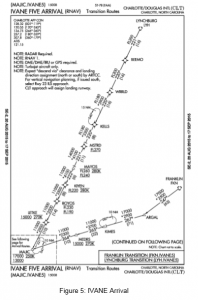
2.6.2 The testing went well, so the FAA designed a procedure meant for general use, the IVANE arrival shown in Figure 5. The stakeholders in the design, testing and implementation process included management and controller union personnel from Charlotte/Douglas Airport (CLT) and Washington and Atlanta area facilities. Also included were US Airways staff, members of the US Airways Pilot Association (USAPA), and staff from FAA Flight Standards and other offices.
2.6.3 Flight Standards conducted computer simulations of early versions of the procedure. The current procedure is shown below. In simulation, the Boeing 737NG would consistently enter an unstable descent after passing through the vertical window FL 240 – FL 260 at MAYOS. This issue plagued the project until it was determined to be a problem with the simulator. There was another issue in which McDonnell Douglas aircraft could not fly the procedure because of a character limitation in their Flight Management System (FMS).
2.6.4 The workgroup tried to manage many other issues, including compression, mixed mode, controller and pilot training, and the question of which facility was to issue the DESCEND VIA clearance. Unlike most procedure in the USA, this one crosses the boundary between two area facilities. Washington Area passes off to Atlanta Area just after MAYOS in Figure 5.
2.6.5 In 2013, the controller union was asking for additional simulation and training, but the FAA was ready to publish and implement the arrival.
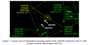
2.6.6 Over the next two years, the use of DESCEND VIA by Washington area controllers was repeatedly authorized and suspended. Controllers found that when aircraft cruising at the MSTRD restriction altitude were issued the DESCEND VIA clearance, they would sometimes descend to FL 240 prior to MSTRD. This is the bottom altitude at MAYOS, the next fix. After multiple incidents an investigation took place.
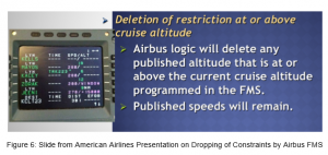
2.6.7 The problem was isolated to one manufacturer, Airbus. Boeing and other aircraft recognize and make the MSTRD restriction. But the Airbus unit made by Thales drops the restriction if the aircraft is in cruise at the restriction altitude. It should only do this if cruising below that altitude, for instance FL 260 between KELLS and MSTRD. US Airways confirmed this issue and briefed their pilots as shown in Figure 6.
2.6.8 The ever-present potential for certain aircraft to descend below their cleared level was a serious operational hazard for controllers at a time when they were just getting familiar with working RNAV Arrival traffic. Controllers who worked incidents as shown in Figure 7 became very skeptical of the procedure. The confusion about the Airbus FMS issue promoted the proliferation of other training issues. The difficulty of correcting the fundamental problem with an existing fleet of aircraft meant controllers and pilots were left developing workarounds, adding anxiety and uncertainty to complex situations.
2.6.9 A related problem for the same Airbus FMS would occur when an aircraft filed or cruised at an altitude below a restriction and then later climbed above the restriction. Once the FMS is notified that the aircraft will cruise below a restriction, it immediately deletes the restriction from the flight plan. The pilot must be aware of this so that upon receiving clearance to climb above the restriction, the procedure would be re-selected and the FMS would then re-apply the restriction. But this is a trap for a pilot.
2.6.10 The original programming of the Thales FMS dates back to the 1980’s. Vertical guidance in procedures of those days told pilots only what to expect; controllers issued explicitly the crossing restrictions. The FMS passed its certification texts and the issue was never observed.
2.6.11 Airbus has been in discussions with pilot and airline representatives over the last several years. They have agreed with the North American Airbus Tech Pilot Group that the current logic is not desirable and have re-engineered the logic to avoid the scenarios described above. This will be a major change and will take a few years before changes are implemented in the aircraft.
2.6.12 Controllers found that training of pilots was a glaring issue. Carriers seem to be relying on email and bulletins with little if any simulation. Guidance such as the below from the National Business Aviation Association (NBAA) web site was disseminated to pilots through various channels.
| The following is an example of the sequence of expected communications using the new IVANE ONE arrival procedure at Charlotte/Douglas International Airport (CLT): Initial Check-in with Washington Center (ZDC): Washington Center: “United One, descend via the IVANE ONE Arrival, Landing South” (or “Landing North” if applicable)
Pilot Response: “United One, descending via the IVANE ONE Arrival, Landing South” On subsequent ATC handoffs, Atlanta Center (ZTL): Pilot initial call: “United One, leaving (current altitude), descending via the IVANE ONE, Landing South” Do NOT use phrases such as the following: • With you Descending On the IVANE • With you on the arrival • Descending via the arrival • With you out of 13,000 for 6,000 • With you via the IVANE |
Still, pilots would regularly question the clearance, particularly as the use of the profile was authorized and then suspended several times. Of course, international pilots would have the additional burden of using this non-ICAO phraseology.
2.6.13 Notice the NBAA guide above doesn’t mention speeds, and there is frequent confusion among pilots about whether they need to adhere to speed restrictions in the procedure. Here is a transcript of a typical exchange on an area frequency on 4 October 2015:
ExecJet955: ExecJet 955 do you need speed 280 at ALDAN?
Washington Area: I just need the published speeds after ALDAN.
ExecJet955: Published speed after ALDAN.
[A minute later] ExecJet955: We’re confusing each other up here. Uh, got a 280 back there at South Boston but didn’t get that and we’re direct ALDAN. Once we get to ALDAN do we need to be at 280, is that correct?Center: Well, my understanding is no. You would not need the 280 at ALDAN. The speed will be your discretion. You just need the next speed – what are we landing, north here? So what would the next speed would be, uh, BLNKR at 210? So that’s my understanding is you do not need the speed because you’re bypassing that fix.
ExecJet955: OK, so BLNKR at 210. So yeah, I just lost the bet, thanks.
Center: Yeah, I know it’s confusing as hell. You guys aren’t the only ones that ask the question. It’s probably something that should’ve been made a little clearer but apparently, it’s not.
ExecJet955: Thank you, sir.
2.7 HYDRR Arrival
2.7.1 Figure 8 shows the HYDRR arrival, a new PBN procedure into Phoenix, Arizona in the USA.
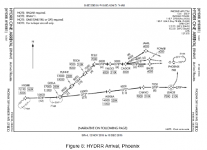
2.7.2 In September 2015, Southwest Airlines informed the FAA that there was a software issue in the FMS of their Boeing 737 aircraft. When flying on a profile STAR in which there are two successive waypoints with hard altitude restrictions, rather than altitude windows, the FMS may disregard the first restriction and calculate a glide path to meet the second restriction. The HYDRR arrival was cited as an example of this situation. Both CHAVO and LEMOE in the lower right of the arrival diagram in Figure 8 have hard altitude restrictions, 9000’ at CHAVO and 7000’ at LEMOE.
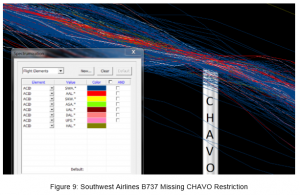
2.7.3 The FAA compiled data on HYDRR arrivals and found that there was a distinct indication of this problem. Aircraft on this procedure were observed missing the 9000’ restriction at CHAVO as shown in Figure 9.
2.7.4 As a result, Southwest Airlines circulated a memo to all of their pilots making them aware of this issue and requiring them to monitor their glide path for potential altitude busts when flying arrivals with profile descents. They include the below text in every flight release headed for Phoenix. They also contacted Boeing and requested a software fix for the problem.
|
***PHX HYDRR ONE ARRIVIAL ANOMLAY*** EVENT – Flight operations ASAP and GE have identified an aircraft anomaly when flying the HYDRR ONE RNAV Arrival, landing west at PHX Prior to passing CHAVO, the aircraft may descend slightly below the 9000 attitude restriction. The anomaly is only at the CHAVO crossing intersection. Pilot action – When flying the HYDRR ONE RNAV Arrival, landing west at PHX, use caution after passing AGGLA to ensure the 9000 crossing altitude at CHAVO is met. Report any anomalies via ASAP as well as to your Dispatcher or the Chief pilot on call. Additional Information – This anomaly has been reported by line Pilots flying the HYDRR ONE RNAV arrivals in both Classic and NG Aircraft. |
2.7.5 Meanwhile, the FAA put out a memo to all of their Phoenix Tracon controllers to “maintain an increased level of vigilance when controlling B737 aircraft on the HYDRR ONE STAR during west flow operations.”
2.8 Washington Metroplex
2.8.1 The Washington DC area has also been the subject of airspace redesign.
2.8.2 PBN arrivals were designed for both Baltimore and Washington National airports. As shown in Figure 9, the two arrivals, CAPSS for Washington National and RAVNN for Baltimore actually conflicted with each other.
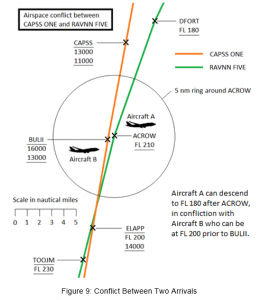
2.8.3 The two fixes, ACROW and BULII are just 0.6 nm from each other. Aircraft A is on the RAVNN FIVE just past ACROW, and can descend to FL 180. Aircraft B is on the CAPSS ONE just prior to BULII, and can be between 13,000 and FL 200 until BULII. The profiles of these procedures are not separated. The procedure designers have not deconflicted the traffic, one of the primary goals of modern airspace redesign. The controller would have to monitor all aircraft on these procedures constantly since they can lose separation with each other without either pilot deviating from the clearance.
2.9 The Airways from Nowhere
2.9.1 In Figure 10, the waypoint in the middle (LAMOB) is the beginning of Y100 (one way route southbound), and the end of B469/L764 – two way routes in Jakarta FIR. An airspace redesign effort intended to create a single one-way route southbound from Singapore to Perth, laterally separated from the northbound route. But the Indonesian part of this was never completed. So two two-way airways meet just one single-direction airway as shown.
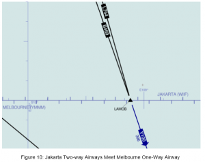
2.9.2 With the airspace design itself flawed, Australian and Indonesian controllers start every day with artificial obstacles to moving traffic. The controllers in Indonesia do not have process for effecting change themselves, so the situation simply festers. There are enough real challenges facing controllers; additional man-made obstacles are not needed.
2.10 IFATCA Policies and Other ICAO References
2.10.1 Doc 9992, Manual on the Use of Performance-based Navigation (PBN) in Airspace Design, says:
| 2.2.6.3 It is important to establish the existing RNAV equipment…actual capabilities and qualifications of the systems being carried and the system upgrades that are expected to be implemented prior to the introduction of the new airspace concept. |
In both the IVANE and HYDRR cases, the FMS equipment were certified years ago. But neither is able to fly new PBN procedures under certain circumstances. Presumably, they would fail certification today. The procedure designer badly needs to know the details of these failings, as expressed in the next section from Doc 9992:
| 2.2.6.3.1 A thorough knowledge of fleet capabilities and a realistic understanding of the likely improvements in capability that will be in place prior to the implementation date are required. |
But must the procedure designer design around avionics limitations when those limitations are failures to perform as required by the ATM system? Having controllers “maintain an increased level of vigilance” is no more than a band-aid solution intended only for very short term mitigation. This kind of requirement can put dramatic stress and workload on the operation.
2.10.2 IFATCA has simple and powerful policy on FMS design:
| AAS 1.12 The flight management system shall accept ATC requirements as compulsory requirements. FMS performance shall be harmonized with ATM system design. |
In the IVANE and HYDRR scenarios, certain FMS units simply do not comply with ATC requirements. Why would that be considered acceptable?
2.10.3 IFATCA also has policy on the operational readiness of automated ATM systems:
AAS 1.3 Operational controllers shall be involved in the design, development and implementation of new ATM systems. Their role should include:
|
One of the concepts behind this policy is that new equipment be treated like a trainee. Certified controllers and others evaluate trainees and ultimately determine whether they should be certified.
2.10.4 IFATCA has Professional policy on the issue as well:
| WC 8.7.4 IFATCA recommends that all parties involved in airport and airspace design address intrinsic safety with the highest priority. |
IFATCA defines intrinsic safety as “safety aspects inherent to the design of the system.” Operational workarounds and equipment that does not meet requirements both diminish intrinsic safety. This is because failures can occur through passivity, i.e. when the human operator does not actively implement the workaround or account for equipment malfunction.
2.10.5 These FMS units with performance issues are already certified. But what if a controller could not keep up with changing requirements? Would other system participants accept this burden and develop work-arounds? No, the controller is required to maintain currency despite constant changes.
Similarly, the community is finding that these FMS units are not able to perform adequately and meet ATM system requirements in modern procedures. The FMS units must either be modified or be designated as ineligible to fly those procedures.
2.10.6 It could be argued that the performance of the FMS is not directly a controller concern, as the primary operator of the FMS is the pilot. But once the pilot makes the entry for the FMS to fly the procedure, it’s the FMS that is flying the aircraft. It’s not practical for human beings to routinely hand fly these complex procedures. Instead, the pilot is the executive director in the cockpit, monitoring and approving the performance of the junior member of the team, the FMS.
All system participants are relying on the FMS to fly the procedure accurately and consistently, the FMS is a key system user, and the FMS must therefore be certified to meet the requirements of the ATM system. An FMS that is known to consistently cause pilot deviations should not be certified but considered a training failure as in 2.10.3 above.
2.10.7 IFATCA has the following additional policies on procedure and airspace design.
2.10.8 The ATS section on Continuous Descent includes this policy:
ATS 3.30 IFATCA defines Continuous Descent Operations as: Continuous Descent Operations (CDO) are aircraft operating techniques facilitated by appropriate airspace and procedure design which meet all ATM requirements, allowing the execution of an optimized descent profile. Doc 9931 should be amended as follows:
|
The “90% rule” refers to designing the procedure such that 90% of trajectories flown in historical data would remain inside the vertical windows.
ATS 3.30 IFATCA defines Continuous Climb Operations as: Continuous Climb Operations (CCO) are aircraft operating techniques facilitated by appropriate airspace and procedure design which meet all ATM requirements, allowing the execution of an optimized climb profile. IFATCA supports the development and implementation of Continuous Descent Operations and Continuous Climb Operations provided that:
|
2.10.9 At the 2015 Conference in Sofia, the following language was adopted as part of the IFATCA Statement on the Future of Global Air Traffic Management:
| Airspace Design and Access Advanced airspace design and procedures are evolving to maximise airspace availability and efficiency. PBN Approaches reduce track distance and can allow aircraft to navigate around terrain in low visibility. Continuous Descent Operations allow operators to maximise fuel economy, RNP standards allow for reduced separation in procedural airspace, increasing capacity and new in-trail climb and descent procedures in en route airspace will allow equipped aircraft to access preferred flight levels. These advanced procedures also have the ability to reduce demand on sector resources. Airspace design that takes advantage of modern aircraft navigation capabilities has the possibility to de-conflict traffic flows, reduce the need for vectoring, and reduce frequency congestion. Advanced airspace design will play an increasingly important role in managing traffic in high-density areas. However, this type of airspace design is only of value if the aircraft operating in the airspace are able to use it.
Airspace analysis and planning is a critical component in developing an airborne equipment based service priority model. Airspace service volumes should be evaluated to determine if and when benefits can be derived from advanced procedures. This evaluation of airspace service volumes should be an ongoing process and can aid in the evolution to a dynamic concept of airspace management and access. By granting access to the most efficient procedures and airspace to aircraft equipped to use them, the business model for airborne investment can be made without artificial manipulation. The demand on controllers to manage a new service priority model is mitigated. Finally, while this model can provide an incentive for operators to equip aircraft, for those that want to defer or delay the on board investment, the option of moving flights away from peak periods to unconstrained periods could improve overall system efficiency and safety. |
Conclusions
3.1 The aviation community is moving towards performance-based navigation (PBN) procedures to improve airspace efficiency, improve climb and descent profiles, reduce flown track distances, reduce separation standards in procedural airspace, increase capacity, save fuel, reduce frequency congestion, de-conflict traffic flows, reduce vectoring and better organize traffic flows.
3.2 Airspace and procedure redesign can successfully realize the above goals when a comprehensive group of stakeholders follows established standards in development, testing, training and implementation.
3.3 Airspace and procedure redesign can be problematic and can be completely dependent on performance characteristics of aircraft and avionics, in particular the Flight Management Systems of different manufacturers. Better FMS standardization would greatly improve, accelerate and reduce the costs of the redesign process.
3.4 ICAO explicitly directs States to involve air traffic controllers with specific local knowledge into the design of airspace at the earliest stage in the process.
3.5 ICAO explicitly directs States to include air traffic controllers as part of the core airspace design team in airspace redesign projects.
3.6 Errors are made in airspace redesign projects worldwide. Controllers do not always have a process for correcting errors made during airspace redesign.
3.7 IFATCA has existing policy on controller involvement in airspace redesign that explicitly call for controller involvement in design, the opportunity for tactical intervention and proper consideration for controller workload. IFATCA views airspace redesign as essential to modernizing airspace.
3.8 Bureaucratically-driven workarounds are some of the most destructive poisons in the operational environment. Controllers have numerous obstacles to successfully completing their mission every day including radio interference, power outages, avionics failures, staffing shortages and more. Depriving controllers of the ability to coordinate airspace changes with neighboring FIRs places an unnecessary and frustrating burden on controllers and adds significant risk.
Recommendations
It is recommended that IFATCA policy is:
4.1 The development, validation and implementation of PBN procedures should involve all affected parties, in particular, local operational controllers and representatives of airspace users.
4.2 Organisational processes, and support should exist for operational staff to initiate airspace and procedure changes.
4.3 The introduction of PBN procedures should be accompanied by training for controllers and pilots that is commensurate with the complexity of the procedure.
References
“Environmental Assessment for Atlanta Optimization of Airspace and Procedures in the Metroplex”, March 2014, FAA
“Understanding Required Navigation Performance (RNP) and Area Navigation (RNAV) Operations”, Universal Avionics Systems Corporation, White Paper, October 2013
“Airspace Concept Handbook for the Implementation of Performance Based Navigation (PBN)”, Eurocontrol, April 2010
“Denver Metroplex Study Team Final Report”, November 2014, FAA Denver Metroplex Study Team
“Houston Metroplex Post-Implementation Analysis”, January 2015, MITRE
SkyVector Aeronautical Library, https://skyvector.com/

