
43RD ANNUAL CONFERENCE, Hong Kong, China (SAR), 22-26 March 2004WP No. 101Developments in the use of Global Navigation Satellite Systems (GNSS) as an Approach AidPresented by SC1 |
Introduction
1.1 Global Navigation Satellite Systems (GNSS) are being introduced at various locations throughout the world as approach aids.
1.2 It is a few years since any new GNSS policy was introduced, or existing IFATCA policy on GNSS reviewed. Previous GNSS policy has been introduced at Ottawa (WP98, 1994) and Santiago (WP93, 1999).
1.3 There has been a proliferation of GNSS approaches around the world since IFATCA last published policy. The concepts surrounding GNSS approaches have developed since the last SC1 paper on the subject. It is therefore time that IFATCA reviewed developments in the use of GNSS as an Approach Aid.
Discussion
2.1 GNSS Overview
2.1.1 GNSS (Global Navigation Satellite System) is a generic term referring to satellite based system. Such satellite systems include the US Department of Defence Global Positioning System (GPS) with barometric altitude augmentation and Receiver Autonomous Integrity Monitoring (RAIM), the Russian GLONASS system, and GPS with Aircraft Based Augmentation System (ABAS), Space Based Augmentation System (SBAS), e.g. EGNOS or WAAS, and Ground Based Augmentation Systems (GBAS).
2.1.2 GNSS sensors are typically approved according to the following standards:
- Technical Standard Order (TSO) 129 / Joint Technical Standard Order (JTSO) 129 Classes A1, B1, C1, B3 or C3 (stand-alone or integrated GNSS receivers with RAIM or equivalent, turn anticipation and a navigation database, approved for non-precision approaches),
- TSO145 or TSO146 (GPS receivers with Wide Area Augmentation System (WAAS) augmentation).
2.1.3 The GPS system, consisting of a constellation of 24 satellites (21 in use and 3 in orbit spares), has been in use since early 1993. The system was developed by the US Department of Defence, but is widely used by civil operators.
2.1.4 There are 3 classes of GPS equipment, each of which have different capabilities. These are detailed below:
- GPS Class A equipment: Equipment incorporating both the GPS sensor and navigation capability. This equipment incorporates RAIM as defined by FAA TSO-C129.
- GPS Class B equipment: Equipment consisting of a GPS sensor that provides data to an integrated navigation system e.g. flight management navigation system, multi-sensor navigation system, (FAA TSOC129).
- GPS Class C equipment: Equipment consisting of a GPS sensor that provides data to an integrated navigation system (e.g. flight management navigation system, multi-sensor navigation system) which provides enhanced guidance to an autopilot or flight director in order to reduce the flight technical error (FAA TSOC129).
2.1.5 Receiver Autonomous Integrity Monitoring (RAIM)
A technique whereby a GPS receiver processor determines the integrity of the GPS navigation signals using only GPS signals or GPS signals augmented with altitude. At least one satellite in addition to those required for navigation should be in view for the receiver to perform the RAIM function (FAA AC 20-138, AC 90-94).
2.1.6 Stand-Alone GPS Navigation System
Stand-alone GPS equipment is equipment that is not combined with other navigation sensors or navigation systems such as DME, Loran-C, Inertial. Stand-alone GPS equipment can, however, include other augmentation features such as altimetry smoothing and clock coasting. (FAA AC 20-138).
2.1.7 GLONASS
(Global Orbiting Navigation Satellite System), is a Russian navigation system, and was declared fully operational in February 1996.
2.1.8 EGNOS
(European Geostationary Navigation Overlay Service) will cover Europe, Africa and Middle East.
2.1.9 Galileo
Is a second generation of GNSS (GNSS-2) that will encompass modernised GPS, the Galileo satellite constellation, together with augmentation systems and different transmissions on separate frequencies, that could be used for all phases of flight.
2.2 The Satellite Navigation concept
2.2.1 The GPS concept works on the basis of each satellite transmitting coded time signals that are compared by the receiver in the aircraft. This comparison of signals from a number of satellites enables the position to be calculated. On modern transport category aircraft, the GPS position is normally fed into a navigation system such as a Flight Management System (FMS). GPS offers the potential for a single system capable of providing navigation guidance for the enroute, approach and landing phases of flight. GPS enables a reduction in ground equipment, so the overall cost of a GNSS system could, potentially, be less than a conventional ground based system.
2.2.2 Three satellites are needed to determine a two dimensional position, and four for a three dimensional position. The elevation and geometry of each satellite relative to the receiver should satisfy certain criteria before the designed system accuracy can be achieved. The use of satellite navigation enables horizontal positions of 100 meters or better to be predicted 95% of time and 300 meters or better 99.99% of the time.
2.2.3 It is generally accepted that to achieve the accuracy and reliability required for Cat I approaches or better, some form of augmentation system is required. A system called Differential GPS uses a ground station at the airport that also receives the satellite signals. As the ground station knows its position very accurately, it can measure any inaccuracy in the satellite signals. The ground station then calculates a correction signal that it transmits to the aircraft on a separate frequency. Differential GPS considerably improves the accuracy of the system, but increases the cost, and removes one of the potential benefits of GPS, that it is independent of ground equipment.
2.2.4 GPS uses the Worldwide Geodetic System 1984 (WGS-84) coordinate system.
2.2.5 Receiver Autonomous Integrity Monitoring (RAIM) in stand-alone GNSS receivers, or a function equivalent to RAIM in integrated GNSS receivers, is essential for airborne use when flying under IFR. In addition to the requirements of the Technical Standard Orders (TSOs), the GNSS equipment must also satisfy all functional requirements laid down in regional criteria, such as JAA TGL-XY.
2.2.6 When the GNSS sensor is the only RNAV sensor in the aircraft (i.e. a stand-alone GNSS system), additional airworthiness approval requirements are required. These additional requirements relate to the following:
- integration of the GPS system into the cockpit,
- annunciation of loss of navigation capability or augmentation capability,
- restriction of pilot-alterable parameters, and
- an assessment of flight crew workload.
2.3 GNSS for the Approach
2.3.1 There are strong drivers to improve the safety of approach and landing operations. Controlled Flight Into Terrain (CFIT) and the so-called “dive and drive” nonprecision approaches are common factors in aircraft accidents and incidents.
2.3.2 Satellite Systems are therefore being introduced for approaches at various locations throughout the world. Different standards exist for such approaches, depending on the region that the aircraft is operating in. Attempts are being made to harmonise the standards and criteria to be applied to GNSS Approaches. These attempts at harmonisation are occurring on both the global and regional scales.
2.3.3 Procedures have been developed and introduced for GPS Approaches. Such procedures are in use at Washington National and at airports in Germany, such as Frankfurt.
2.3.4 GPS-based navigation equipment can be used to fly any part of instrument nonprecision approaches provided each of the following conditions are met and checked, as required during pre-flight planning:
a) The State of operator/registry (as applicable) has authorised the use of multi-sensor equipment using GPS as one sensor or GPS Class A1 equipment for this purpose;
b) the State of the aerodrome has authorised/published an approach for use with GPS;
c) the published approach procedure is referenced to WGS-84 co-ordinates;
d) the navigation database contains current information on the non-precision approach to be flown (actual AIRAC cycle);
e) the approach to be flown is retrievable from the database and defines the location of all navigation aids and all waypoints required for the approach; the information stored in the data base is presented to the crew in the order shown on the published non-precision approach plate;
f) the navigation data base waypoints showing the non-precision approach cannot be changed by the flight crew;
g) the appropriate airborne equipment required for the route to be flown from the destination to any required alternate airport and for an approach at this airport, is installed in the aircraft and is operational. Also, the associated ground-based navaids are operational.
2.3.5 Whilst GPS is considered to be suitable for Non Precision Approaches, it is expected that Local Area Augmentation Systems (LAAS) will be necessary to support GNSS Cat. II/III landing operations.
2.3.6 GNSS approaches must be selectable from the navigation database. The coding of the approach in the navigation database will need to support the officially published approach.
2.3.7 A GPS stand-alone approach refers to a non-precision approach procedure based solely on GPS without reference to conventional ground navaids. In addition to the paragraphs above, each of the following conditions apply:
a) the integrity monitoring function (RAIM or equivalent) is available,
b) compliant Class A1 equipment is fitted;
c) the published approach procedure is identified as a GPS approach (e.g.: GPS RWY 27; during the pre-flight planning stage for an IFR flight:
-
- where a destination alternate is required, a non-GPS based approach procedure is available at the alternate;
- where a destination alternate is not required, at least one non-GPS based approach procedure is available at the destination aerodrome;
- predictive RAIM or an equivalent prediction tool is used, and
- the monitoring capability (RAIM or equivalent) is available at the destination aerodrome at the expected time of arrival.
d) where a take off and/or en-route alternate is required, at least one non-GPS based approach procedure is available at the alternate(s).
e) a missed approach procedure is available based on traditional navigation.
2.3.8 Loss of GNSS positioning will normally occur when the GNSS receiver has insufficient satellites in view. A minimum of three satellites is needed for a position fix in two dimensions. An additional satellite is required for a third dimensional position fix. Due to the extremely low power of GPS signals, the signal-in-space can easily be disturbed by unintentional interference, or become shielded by mountainous terrain. The GPS receiver warns the crew (using RAIM) when the integrity of the position cannot be guaranteed. This requires an additional satellite.
2.3.9 The probability for total loss of GNSS signal-in-space is reportedly 10-4 (failure rate of all signals in view).
2.3.10 Note that in case of a general GNSS signal-in-space failure, all GNSS-only aircraft in the area are affected. It is recognised that this bears a serious safety risk due to a significant increase of ATC workload and a possible ATC frequency congestion. However, as interactions of multiple aircraft fall outside the scope of this study, the effect of simultaneous loss of GNSS for several aircraft was not studied here. This should be assessed in application specific safety cases.
2.4 Space Based Augmentation Systems
2.4.1 There are several Spaced Based Augmentation Systems being developed. Examples include EGNOS in Europe, Wide Area Augmentation System (WAAS) in the United States, CWAAS in Canada, and MSAS in Japan.
2.5 Ground Based Augmentation Systems
2.5.1 The introduction of Local Area Augmentation Systems (LAAS) in the United States is an example of GBAS systems being deployed for operational use. The purpose of GBAS is to augment GNSS equipment and allow greater accuracy during the final approach segment of flight.
2.6 RNP-RNAV for Approach
2.6.1 There are various types of RNAV approach in use throughout the world. Standards vary considerably from State to State or region to region, and procedures are available in locations as diverse as Juno in Alaska, the Caribbean, Europe and southern Africa. The concept of RNP-RNAV is being introduced in an attempt to produce a common, global standard and harmonise the diverse GPS and FMS procedures that have previously been produced. RNAV approaches are in use throughout the world. Harmonisation is required so as to ensure that aircrews don’t have to face differing procedures depending on where they are operating.
2.6.2 Safety initiatives, such as US Commercial Aviation Safety Team (CAST) and JAA Joint Strategy Safety Initiative (JSSI), advocate Continuous Descent Procedures that have inherent in them a stabilised, constant angle approach path. Flight Guidance Systems on modern aircraft offer the ability to fly approaches with lateral and/or vertical navigation (LNAV and VNAV using either coupled autopilot or Flight Director) providing a “precision-like” capability. ICAO Annex 6 refers to these types of procedure as Approach with Vertical Guidance (APV).
2.6.3 RNP-RNAV is being implemented on instrument approach procedures to provide increased availability, enhanced safety and reduced operating minima over and above that provided from traditional non-precision approaches.
2.6.4 The RNP-RNAV concept specifies the Required Navigation Performance of an aircraft in order to fly the approach. GNSS systems are not mandated as a matter of course. Certain RNP values can be met by DME/DME updates. However, as the RNP values becoming smaller, and more precise navigation is required, GNSS becomes required as other conventional means of navigation cannot provide the level of accuracy needed.
2.6.5 The RNP aspect of the acronym stands for Required Navigation Performance (RNP) and is a statement of the navigation performance accuracy necessary for operation within a defined airspace.
2.6.6 The table below shows the types of RNP that are currently in use or are being considered for Approach use:
| RNP Value | Required Accuracy (95% Containment) | Description |
| 0,003/z | ± 0.003 NM [± z ft] | Planned for CAT III Precision Approach and Landing including touchdown, landing roll and take-off roll requirements. (ILS, MLS and GBAS) |
| 0,01/15 | ± 0.01 NM [± 15 ft] | Proposed for CAT II Precision Approach to 100 ft DH (ILS, MLS and GBAS) |
| 0,02/40 | ± 0.02 NM [± 40 ft] | Proposed for CAT I Precision Approach to 200 ft DH (ILS, MLS, GBAS and SBAS) |
| 0,03/50 | ± 0.03 NM [± 50 ft] | Proposed for RNAV/VNAV Approaches using SBAS. |
| 0,3/125 | ± 0.3 NM [± 125 ft] | Proposed for RNAV/VNAV Approaches using Barometric inputs or SBAS. |
| 0,3 | ± 0.3 NM | Supports Initial/Intermediate Approach, RNPRNAV Approach, and Departure. Expected to be the most common application. |
| 0,5 | ± 0.5 NM | Supports Initial/Intermediate Approach and Departure. Only expected to be used where RNP 0.3 cannot be achieved (poor navaid infrastructure). and RNP 1 is unacceptable (obstacle rich environment). |
| 1 | ± 1.0 NM | Supports Arrival, Initial/Intermediate Approach and Departure; also envisaged as supporting the most efficient ATS route operations. Equates to P-RNAV. |
Table 1 – RNP Types for Approach
2.6.7 A range of RNP types were defined from RNP 1 to RNP 0.003/z, where z reflects the requirement for vertical guidance. ICAO’s GNSSP has proposed a set of values which could be supported by Space Based Augmentation Systems (SBAS) and Ground Based Augmentation Systems (GBAS).
2.6.8 The concept of RNP-RNAV is introduced in the Minimum Aviation System Performance Standards (MASPS) for Required Navigation Performance for Area Navigation (RNP-RNAV), (reference: RTCA DO 236A / EUROCAE ED 75).
2.6.9 RNP-RNAV combines the accuracy standards laid out in the ICAO Manual (Doc 9613) with specific containment integrity and containment continuity requirements, as well as functional and performance standards for the RNAV system to realise a capability that can meet future ATM requirements.
2.6.10 The table below shows the required parameters for RNP-RNAV:
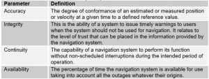
Table 2: Navigation Performance Parameters
2.6.11 Many RNAV systems also have the capability of providing vertical navigation (VNAV). VNAV presents to the pilot computed vertical guidance referenced to a specified vertical path angle (VPA). The computer-resolved vertical guidance may be based on barometric altitude (baro-VNAV) or geometric altitude (e.g. from the GNSS – geometric VNAV) and is either specified as a vertical path angle to a waypoint or as a geometric path between two waypoints.
2.6.12 The RNP value defines the total navigation system error (TSE) that is allowed in lateral, longitudinal, and, in some cases, vertical dimensions within a particular airspace. The TSE takes account of navigation system errors, RNAV computation errors, display errors and flight technical errors. The TSE must not exceed the specified RNP value for 95% of the flight time on any part of any single flight.
2.6.13 Aircraft operators wishing to conduct RNAV approach operations have to prove to the authorities that their aircraft have the capability to safely fly these approaches and that the operating procedures followed by the flight crew are up to the task. The Joint Aviation Authorities (JAA) are currently developing airworthiness and operational approval criteria for RNAV approach operations.
2.6.14 The regulations covering the design of RNAV approach procedures must enable the operator to safely fly them. The ICAO Obstacle Clearance Panel (OCP) is developing instrument procedure design criteria for RNP-RNAV and the ICAO Separation and Airspace Safety Panel (SASP) is considering the separation criteria for RNP-RNAV. To date, instrument procedure design criteria are only available for RNP 0.3 approaches.
2.6.15 Air traffic service providers offering these procedures must adapt their practices to these procedures.
Conclusions
3.1 There is a need to harmonise the variety of GNSS approaches that exist throughout the world. The concept of RNP-RNAV enables a degree of standardisation and commonality to be introduced to the previously diverse applications of GNSS for approach use.
3.2 For procedures where aircraft rely only on GNSS, the responsible authority should consider the acceptability of the risk of loss of RNAV capability of multiple aircraft due to satellite failure or RAIM holes.
3.3 Standardised R/T phraseology appropriate to GNSS approach operations must be promulgated.
3.4 Controllers need to be aware of the navigational capability of individual aircraft so as to know whether an aircraft can be cleared on a specific type of approach. For instance, RNP 0.3 approaches typically require aircraft to be GNSS equipped. The controller therefore needs to know which aircraft are suitably equipped for such an approach. ICAO Annex 11 states that : “ATS units shall be kept currently informed of the operational status of non-visual navigational aids. Information on the operational status, and any changes thereto, should be received by appropriate ATS units on a timely basis consistent with the use of the aid(s) involved”. The current ATS Flight Plan as regulated by PANS RAC allows for only the notification that the aircraft is equipped with a GNSS sensor or receiver (letter G) or that the aircraft meets the RNP type for all route segments and airspaces during the flight (letter R).
Since in contrast to current conventional navigation practice, RNAV capabilities vary widely among aircraft, and RNAV approach procedures can be diverse to accommodate these different capabilities, it may be necessary to provide a more detailed system for conveying aircraft capabilities information.
3.5 Where reliance is placed upon the use of radar to assist for contingency procedures, the radar performance has to be adequate for that purpose, and the requirement for a radar service is identified in the AIP. Note: according to the ICAO RNP Manual, terminal area radar fix tolerance within 20 NM is ±0.8 NM, which is larger than the fix tolerance of most RNAV approach procedures.
3.6 The introduction of RNP-RNAV approaches enables the concept of RNAV to be extended to the approach phase. RNP-RNAV approaches will be the final segment in a series of RNAV procedures, starting with an RNAV SID, an RNAV route for the en-route segment, linking to an RNAV STAR, followed by an RNAV Initial Approach Procedure and culminating in the RNP-RNAV Approach. An endto-end RNAV concept becomes a reality with the advent of RNP-RNAV approaches.
Recommendations
It is recommended that;
4.1 SC1 actively monitors developments in the use of RNP-RNAV for approaches.
4.2 This paper is accepted as information material.
References
TGL-3 REV 1: JAA Interim Guidance Material on Airworthiness Approval and Operational Criteria for the Use of the Navstar Global Positioning System (GPS). December 1997.
ICAO: “Procedures for Air Navigation Services – Aircraft Operations”.
Eurocontrol: “Guidance Material for the Design of Terminal Procedures for Area Navigation (DME/DME, B-GNSS, Baro-VNAV & RNP-RNAV”.
“United States Standard for Terminal Instrument Procedures (TERPS)”.
IFATCA – Ottawa 1994, WP98.
IFATCA – Santiago 1999, WP93: The Use of GNSS – ATC.

