50TH ANNUAL CONFERENCE, Amman, Jordan, 11-15 April 2011WP No. 95Review Continuous Descent Operations ManualPresented by TOC |
Summary
Recent experience has proven the potential of new arrival procedures known as Continuous Descent Arrivals (CDAs). CDAs enable aircraft to make a more continuous descent from cruise to runway, saving fuel, reducing emissions, and reducing frequency congestion. ANSPs want to expand the use of CDAs. To regulate this activity, ICAO has produced Doc 9931, “Continuous Descent Operations Manual”. This paper reviews the Manual and guidance to Member Associations.
This paper proposes new policy including a definition of Continuous Descent Operations, requirements for CDO development and deployment, and specific changes to Doc 9931.
Introduction
1.1
“Recent volatility in jet fuel prices and growing environmental sensitivity have stimulated investigation into methods for reducing air transportation fuel consumption, pollutant emissions and noise in the next generation of air traffic management (ATM). Within the descent phase of flight, a concept of operations for reducing these aspects is to redesign flight arrival routes and procedures such that jet aircraft can reduce the application of throttle … By allowing their engines to remain at idle during descent, descending aircraft can minimize the fuel burned, the exhaust gases vented, and the noise generated by the engines.” (Shresta et al., 2009)
1.2 This new class of procedures is called Continuous Descent Operations (CDO).
1.3 Fuel and emissions savings are realized by eliminating level flight segments as shown in Figure 1.
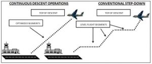
Figure 1: Conventional vs. CDO Vertical Profile
1.4
“In the most ideal form of [continuous descent], a descending aircraft will not apply any throttle during descent. Instead, the potential and kinetic energy of the descending and decelerating aircraft will be managed optimally. The arriving aircraft will be able to glide down from cruise with its engines set to idle while transferring its kinetic and potential energy into the drag on the airframe. In that case, the fuel burned and pollutants emitted during arrival will be minimized. This is what is generally known as a continuous descent arrival (CDA).” (Shresta et al., 2009)
1.5 Studies have indicated that, for a typical airline jet, levelling off and speed adjustment during a traditional arrival trajectory “consume as much as a 55-gallon barrel of jet fuel more than a constant, idle power descent.” By using continuous, idle-power descents in just one US city, Seattle, Washington, over 2 million gallons of fuel yearly could be saved and carbon emissions could be reduced by 22,400 metric tons annually – the amount emitted by 4,100 cars in one year. (Gillie, 2009)
1.6 To get ahead of the global development of these procedures, ICAO has published Doc 9931, the Continuous Descent Manual, intended to regulate and assist designers and to foster global harmony.
Discussion
CDA Definition and History
2.1 CDA Definition
2.1.1 ICAO Doc 9931 paragraph 1.1.1.1 describes Continuous Descent Operations (CDO) as follows:
Continuous Descent Operations CDO is an aircraft operating technique aided by appropriate airspace and procedure design and appropriate air traffic control (ATC) clearances enabling the execution of a flight profile optimized to the operating capability of the aircraft, with low engine thrust settings and, where possible, a low drag configuration, thereby reducing fuel burn and emissions during descent. The optimum vertical profile takes the form of a continuously descending path, with a minimum of level flight segments only as needed to decelerate and configure the aircraft or to establish on a landing guidance system (e.g. ILS).
2.1.2 This definition considers only the ideal fuel and emissions performance of a single aircraft. Procedures constructed on this basis are naturally going to be inefficient and even disruptive to other traffic and other system users.
2.1.3 The term “Continuous Descent Operations” is itself not a procedure but a class of procedures. The procedures are called Continuous Descent Approach (CDA), Continuous Descent Arrival, or, in the United States, Optimized Profile Descent (OPD). US controllers prefer their term because the word “continuous” suggests the pilot’s ideal descent path, 3° at idle with no wind. The reality at busy airports will never provide that, but will instead provide an “optimum” path based on the needs of all aircraft and the controller. The acronym CDA will be used in this paper to refer to any continuous descent procedure.
2.2 United Kingdom
2.2.1 The United Kingdom has developed considerable experience with CDAs at Heathrow, however, their work is exclusively focused on reducing noise. As a result, British CDAs begin only at 7000 ft, not from cruising levels. From one of their publications,
“The stage of flight where the increased use of CDA can improve the noise climate is from the holding stack to the joining point.” (BAA, 2007)
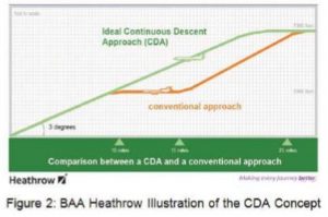
2.2.2 The BAA figure below (Rafano, 2010) shows the CDA beginning at 7000 ft. It also shows the ideal descent path under zero wind conditions, a trajectory making a 3° angle with the ground. BAA is mostly concerned with eliminating the orange portion of the trajectory because it represents noise pollution.
2.3 Los Angeles International
2.3.1 As a component of its Trajectory-Based Operations NextGen initiative, the FAA has authorized development of arrival procedures with vertical profiles optimized to facilitate a continuous descent from the top-of-descent to touchdown – as much as possible.
2.3.2
“In Los Angeles, KLAX airport (3) Optimized Profile Descents…[were]…implemented. The OPD RNAV STARS affords 50% of LAX traffic an OPD arrival – a more than 5-year process with a 96% compliance with the vertical profile. This results in fuel savings of over 2 million gallons annually. Reductions in CO2 emissions estimated at over 41 million metric tons annually.” (IATA, 2010)
2.3.3 The example of KLAX OPDs is considered by some as the “gold standard” for continuous descent operations. KLAX proved the concept could succeed in complex busy airspace. Previously, many in the industry felt it was impractical in such applications.
2.4 The Los Angeles CDA Design Method
2.4.1 The methods used to design the successful CDAs at KLAX are of great interest to TOC.
2.4.2 Active air traffic controllers from the arrival sectors were included in the team from the start.
2.4.3 KLAX CDA designers first focused on the impossibility of building a procedure that would suit every airplane and every FMS in every atmospheric condition. As a result, KLAX CDA designers devised the “90% rule”. CDA design can never be a one-size-fits-all. This rule is explained in the following step-by-step process they used to develop CDAs:
1. Build the design team with active controllers who work the arrival traffic.
2. Obtain data on typical trajectories at the selected airport. This data should encompass a wide range of atmospheric conditions as well as a representative sampling of aircraft types and FMS boxes. In the US, the airlines provided this data.
3. Define the lateral and vertical confines within which 90% of these trajectories would remain. Make adjustments to insure that this envelope is not an unreasonably large volume of airspace. This is a key point, as the envelope must be minimal in complex, busy airspace to accommodate other operations.
4. Build an initial CDA around this envelope.
5. Do not target an “ideal” descent path from top-of-descent (TOD) to the runway because this is not practical in complex airspace. Rather, break the full trajectory into a few segments, built around merge points – where two or more flows of arrivals join. During each segment, the FMS would not have its sights set on the runway but instead would be aiming to hit a particular fix within a small altitude range.
6. Finalize the design using a trajectory simulation tool to demonstrate adherence to the 90% rule. The KLAX CDA designers used TARGETS (Terminal Area Route Generation, Evaluation and Traffic Simulation built by MITRE – https://www.caasd.org/work/project_details.cfm?item_id=152).
7. Perform additional simulation testing on the finalized design.
8. Redesign the associated sectors around the new CDA. This is a critical piece as well since the CDA must reside in the minimum number of sectors to reduce complexity.
9. Perform simulation testing with certified controllers and make adjustments as indicated.
10. Begin implementation process.
2.4.4 The resulting CDA is not to be treated as prohibited airspace. The sectors can continue to accommodate non-arrival aircraft and other flows of traffic as determined by the controller in real time.
2.4.5 After implementation, KLAX designers found the success of the CDA hinges on precisely spaced arrival traffic. The situation is very fluid, being dependent on winds and other atmospheric conditions that could cause a “pile up” close to the runway. If the CDA controller must apply vectors or dramatic speed changes, the CDA becomes a liability to the controller and inefficient.
2.4.6 Presently, KLAX controllers must actively manage their arrival restrictions by manual methods involving, at some point, an individual’s judgement. Unusual winds can wreak havoc on the CDA flow. This is not ideal. Automated, advanced and accurate spacing tools are ultimately essential to the success of CDAs.
2.5 Atlanta Hartsfield International
2.5.1 The busiest airport in the world, Atlanta, is very proactive in the use of new technologies. KATL may publish a new CDA as soon as August 2011, but implementation will probably be delayed because automated spacing tools are not yet adequate to provide the well-spaced streams required. The KATL environment is more complex than KLAX because there are so many more inbound streams and they are coming from virtually all directions. Larger numbers of merge points and de-confliction points in both en route and approach airspace make the KATL flows more sensitive to spacing.
2.5.2 KATL tried experimental CDAs with “descend via” clearances in the past. Altitude violations skyrocketed because controllers had to make too many spacing corrections within the CDA. The current en route spacing tools are not robust enough to accomplish spacing prior to the CDA entry point.
2.6 US Lessons Learned
2.6.1 CDAs require a precisely spaced arrival flow. The spacing required changes depending on conditions, and those conditions can change hour by hour and even minute by minute. Sudden wind changes can disrupt into the CDA flow and turn a dense but orderly sector into chaos.
2.6.2 Ultimately, automated wind information is essential to widespread use of CDAs. The wind data must be accurate and continuously updated. Forecasts, pilot reports and local observations are not adequate for the needs of the CDA. Automated electronic reporting by aircraft is viewed as a potential source of this wind data. CDA operation becomes more practical when a reliable and accurate source of wind data is available.
2.6.3 As stated previously, the 90% rule is advised in CDA design and CDAs should be built not to provide a continuous descent from cruise to runway, but to provide continuous descents to each segment end point.
2.6.4 The experiences of KLAX and KATL are of great value to CDA designers worldwide and point towards the following best practices:
- Active controllers from the arrival sectors should be on the design team.
- CDA design should be focused on building a flight envelope that 90% of the typical traffic in an ideal, engine-idle descent will remain within during typical atmospheric conditions. Attempts to provide greater applicability will consume too much airspace to be practical in busier airspace. The 90% figure is a target only.
- For the use of CDAs to expand beyond individual, heavily monitored applications, two technologies will need to mature:
- Automated wind data – This will be needed by both the FMS and by the air traffic system.
- Automated sequencing systems – These will incorporate automated wind data to enable air traffic control to continuously supply a changing spacing interval to the CDA, to enable a precisely spaced flow of aircraft at the exit point of the CDA, the runway. Without automated spacing, CDAs decrease safety at large airports such as KATL.
- Simulation is an essential, “must-have” element of CDA design at more than one point in the development process.
- Dynamic sectorization is not an essential element of CDA design.
CDO Manual: Review
2.7 General Review of the Manual
2.7.1 The Manual cites these two goals as primary:
- enabling uninterrupted continuous descents
- increasing flight predictability
2.7.2 Regarding flight predictability, the Manual should be more specific and discuss it from both the pilot’s perspective and the controller’s. CDA’s can vary widely in how much flexibility the pilot has to determine the top-of-descent (TOD) point and the descent rates throughout the procedure.
2.7.3 From the pilot perspective, the ideal CDA would allow a large range of TODs and would also provide a large range of altitudes along the entire path to the runway. This way, the pilot could accommodate varying wind and load conditions, aircraft type and other factors to achieve the perfect, engine-idle descent from TOD to touchdown. TOC would consider such a CDA to be “high tolerance”.
2.7.4 From the controller perspective, a high tolerance CDA would actually decrease flight predictability. While the controller would know that the aircraft will remain within the CDA 3D envelope, that envelope would likely consume so much airspace that the trajectory of successive aircraft would vary tremendously. The CDA envelope would occupy an enormous amount of airspace such that the design of the airspace and the ability to get crossing traffic through the sector would be compromised.
2.7.5 By contrast, a “low tolerance” CDA that confines the trajectory to a tightly constricted envelope would provide the controller with a highly predictable flight path but would often fail to provide the aircraft with the highly efficient and low emissions path from cruise to touchdown that is the primary goal of Continuous Descent Operations.
2.7.6 The tug-of-war here is the struggle between giving aircraft a large flight envelope in which to choose the best descent profile, and restricting the aircraft’s descent to a narrow channel to give the controller more flight predictability and as much airspace to work with as possible. The Manual does not identify this issue nor address it. But the designers of the LAX CDAs understand this well and this is the basis for their “90% rule” that provides a compromise between aircraft efficiency and airspace efficiency.
2.8 Open Path Design
2.8.1 The Manual spells out two general design methods, open path and closed path.
2.8.2 Open path is described in paragraph 1.2.1.5.2:
The open path design is a design where a portion, or all, of the route consists of vectoring. The specific distance to runway threshold is not known prior to start of the CDO.
2.8.3 This method has 2 procedures:
- Vectored CDA Procedure – The aircraft is vectored and the pilot is given with the distance estimate Information to the runway threshold, the descent clearance is at pilot discretion.

Figure 3: Vectored CDA Procedure
- Open CDO Procedure to Downwind – Is combined with a fix route, delivering the aircraft to a vectoring segment, normally as an extension of the downwind leg to the FAF/FAP.
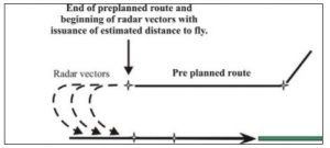
Figure 4: Open CDA Procedure to Downwind
2.8.4 The Vectored CDA Procedure increases pilot and controller workload and reduces predictability from the pilot standpoint. It is more a tactical solution than strategic one. This procedure requires more pilot controller communication as vectoring provides the least advanced predictability for pilots to plan ahead.
2.8.5 The Open CDA to Downwind Procedure can be considered a partially closed procedure. Although most of the lateral path is fixed, the last part remains ‘open’ to retain flexibility. An optimum descent however cannot be planned because the complete route is not known. All Open Path CDAs call for the controller to advise the pilot of the distance to the runway.
2.9 Closed Path Design
2.9.1 Closed Path is described in paragraph 1.2.1.5.1.1:
The closed path design is a design where the route is fixed and the specific distance to the runway is known prior to start of the continuous descent operation. The procedure may be published with crossing levels, level windows and/or speed constraints. The design of the closed path may comprise the STAR and (initial) approach phases of flight until the FAF/FAP final approach point (FAP).
2.9.2 This procedure gives pilots maximum predictability by the fact that the exact distance to be flown is precisely known. The effect on the controller is to restrict the use of vectors. Thus the use of Closed Path CDAs relies heavily on automated spacing methods.
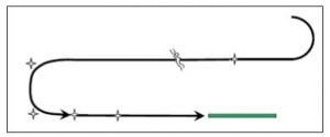
Figure 5: Closed Path Design
2.10 Path Stretching
2.10.1 Path Stretching allows flexibility in a closed path CDA to provide the controller with a means to adjust the spacing.
2.10.2 Path Stretching is a planned vectoring procedure that has waypoints incorporated known for the pilot, the FMS, and the controller. Some Path Stretching can be seen in the River One Arrival to KLAX in the Appendix.
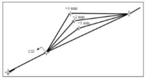
Figure 6: Path Stretching
2.11 Merge Point
2.11.1 Merge Point is described in paragraph 1.2.1.5.4.2:
With this technique, aircraft follow an RNAV routing, which generally includes a level flight arc segment until receiving a ‘direct to’ routing to a merge point. The pilot may execute a CDO prior to the merge point arc, maintain level flight whilst following the arc and continue with CDO when cleared to the merge point. When traffic levels permit, the aircraft would be cleared direct to the merge point rather than establishing on the arc.
2.11.2 Merge Point, like Path Stretching, builds spacing options into the closed path CDA to allow the controller more “wiggle room”. A generic depiction is shown in Figure 7.
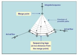
Figure 7: Merge Points
Conclusions
3.1 The CDO Manual incorrectly uses the term “CDO” to refer to a procedure. A specific procedure is either a Continuous Descent Arrival (CDA) or an Optimized Profile Descent (OPD).
3.2 The ICAO definition of Continuous Descent Operations is not in line with the intent of the Manual as it only considers the perspective of a single aircraft and its fuel burn and emissions.
3.3 Flight predictability should be increased for both the aircraft and the ATM system.
3.4 Recent implementations provide good material for developing best practices for CDA design. The involvement of controllers in these cases was critical to the success of the new procedures.
3.5 Open Path CDAs are a compromise between flight path predictability and controller flexibility.
3.6 In CDA design, there is a trade-off between capacity and the aircraft’s optimal flight path. A low tolerance CDA gives controllers higher predictability and higher capacity for non-arrival traffic, but will often inhibit aircraft from flying an ideal engine-idle trajectory. A high tolerance CDA enables pilots to fly ideal descent trajectories, but severely reduces the capacity of the sector for nonarrival traffic and decreases flight predictability for the controller.
3.7 Restrictions on the controller’s ability to intervene in the flight path reduce ATM capacity.
Recommendations
It is recommended that;
4.1 IFATCA policy is:
IFATCA defines Continuous Descent Operations as:
Continuous Descent Operations (CDO) are aircraft operating techniques facilitated by appropriate airspace and procedure design which meet all ATM requirements, allowing the execution of an optimized descent profile.
and is included in the IFATCA Technical and Professional Manual.
4.2 IFATCA policy is:
IFATCA supports the development and implementation of Continuous Descent Operations provided that:
- Controllers are involved in the design.
- Airspace is suited to the design.
- The design meets the desired ATM capacity.
- Tactical ATC interventions are allowed.
- Flight predictability is increased for both pilots and controllers.
- Controller workload is not increased beyond an acceptable level.
and is included in the IFATCA Technical and Professional Manual.
4.3 IFATCA policy is:
Doc 9931 should be amended as follows:
- Incorporate CDA design practices learned, including the 90% rule, the use of extensive simulation and the need for automated wind data and advanced sequencing tools.
- More precisely refer to those procedures it aims to regulate as either Continuous Descent Arrivals (CDAs) or Optimized Profile Descents (OPDs).
and is included in the IFATCA Technical and Professional Manual.
References
“Analysis of Continuous Descent Benefits and Impacts During Daytime Operations” Sanjiv Shresta, Dejan Neskovic, and Stephen S. Williams, MITRE Center for Advanced Aviation System Development, ATM 2009, June 29-July 2, 2009, Napa, California.
“Alaska Air tests fuel-saving landing procedure”, John Gillie, The Seattle News Tribune, August 30, 2009 [https://www.komonews.com/news/local/56243327.html].
BAA Heathrow – Flight Evaluation Report 2007
[https://www.baa.com/assets//B2CPortal/Static%20Files/Noise%20Booklet.pdf].
“CDA at London Heathrow”, Peter Rafano, Flight Analysis Manager, 23rd September 2010.
IATA Flight Bag Newsletter, September 2010, [https://www.iata.org/whatwedo/safety_security/newsletter/september-2010/Pages/regionalupdates.aspx]
Appendix A – Specific Commentary from LAX CDA Designers
The following are specific critiques of Doc 9931 by the principal air traffic controllers involved with the design of the CDA procedures at LAX. TOC does not necessarily endorse these views, but considers them very credible and wants to broadcast them to enhance debate.
1. Paragraph 1.1.2.2:
This necessitates that the level and speed windows of standard instrument arrivals (STARs) and approach procedures be designed to take account of aircraft performance limits and be executed with a good knowledge of wind data available to the pilot by manual entry or data link.
Only automated, precise wind information will provide adequate data for arrival management in a CDA.
2. Paragraph 1.1.2.4:
For optimum traffic handling in busy periods at high capacity airports, air traffic controllers may need to use tactical intervention, i.e. vectoring and/or speed control, to sequence and separate aircraft.
The experience at KATL suggests that tactical intervention within the CDA is inadvisable.
3. Paragraph 1.1.4.7:
A CDO that is facilitated by the controller providing timely estimates of distance-to-go information to the pilot when being vectored may only be possible for lower altitudes and may offer less than fully optimal performance improvement.
Supplying pilots with distance-to-go information is not a practical method in busy, complex airspace.
4. Paragraph 1.1.4.8:
Arriving and departing traffic are usually interdependent and the airspace design supporting CDO should ensure that both arriving and departing flights can achieve fuel efficient profiles.
Continuous climb provides much more benefit than continuous descent. There should be a bias towards continuous climb, not a balance between the two.
5. Paragraph 1.2.1.1:
Accurate planning for an optimum descent path is facilitated by the pilot and/or the FMS knowing the flight distance to the runway, and the level above the runway from which the CDO is to be initiated.
The Manual puts too much focus on the runway. The KLAX experience showed that the trajectory should be segmented, with the FMS focusing on the next merge point.
6. Paragraph 1.2.1.5.3:
The following three sequencing methods can be applied to both types of CDO.
There are only two sequencing methods, vectoring and speed. Required time of arrival, traffic management advisory, and relative position indicators are tools, not methods.
7. Paragraph 1.3.2.2:
However, where the airspace can support descent profiles between 2 and 3.3 degrees, there will be little requirement for modelling…
The only true constraint to 3° glide path is terrain. If there is no terrain within 2 nm of the threshold, then curved path 3° glide paths are available.
8. Paragraph 1.3.4.1:
Feedback from flight simulations is one way to ensure that the proposed design does not adversely affect aircraft and/or that it can facilitate CDO being available to the majority of the expected aircraft fleet…
Flight simulation should not be thought of as an option. It is essential to proving the design.
9. Paragraph 1.3.6.1a:
The controller provides the pilot with an estimate of the flight track-miles to the runway threshold as distance-to-go information.
This is another example of how pilot-centric this document is. Providing the pilot with estimated flight track miles would be very difficult with even medium density operations.
10. Paragraph 1.3.7.1:
Additional tools for ATC to manage the spacing and sequencing process may increase the level of CDO achieved.
The term “level” in this case seems inappropriate. “Amount” would be more precise.
11. Paragraph 2.2.3.1
Aircraft/FMS specific limitations should also be taken into account.
Consideration for specific aircraft undermines the “90% rule”. Representative fleet performance should be the driver of CDA design.
12. Paragraph 2.3.1.1
Maximum effective execution of published CDO procedures using laterally and/or vertically defined routes requires flexible airspace design and sectorization…
The practicality of flexible sectors and airspace has never been demonstrated. The experience at KLAX is that airspace and sectors do not need to be flexible.
13. Paragraph 2.3.2.1
Traffic demand may dictate tactical interventions by the controller on arrival flows so as to achieve the maximum landing rate. Pre-sequencing of the traffic prior to the merge point is essential to achieve the maximum capacity when using closed path CDO procedures. The more effectively aircraft are sequenced and merged, the greater the likelihood that aircraft can maintain the optimum rate of CDO. Pre-sequencing may be effected by tactical lateral path stretching using vectoring or point merge techniques) and/or speed control.
Traffic demand will dictate tactical interventions to achieve the maximum landing rate. The last part of this message should be front-and-center in this document. Pre-CDA sequencing is crucial.
14. Paragraph 3.1.1.1b:
CDO down to FAP/FAF/IF/IAF may not always be appropriate. However, a hybrid approach of a CDO procedure to a specified level and waypoint, followed by vectors to the FAF/Final approach course may be a viable solution.
Here is where the Manual does back off from its focus on designing for continuous descent to the runway. But this message is buried in the document and should be stronger and brought much closer to the surface.
Appendix B – CDAs from Munich, Los Angeles, and Mexico City
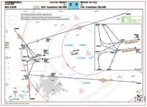
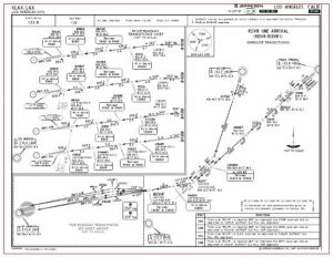
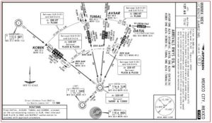
CDAs from Munich, Los Angeles, and Mexico City


