
DISCLAIMER
The draft recommendations contained herein were preliminary drafts submitted for discussion purposes only and do not constitute final determinations. They have been subject to modification, substitution, or rejection and may not reflect the adopted positions of IFATCA. For the most current version of all official policies, including the identification of any documents that have been superseded or amended, please refer to the IFATCA Technical and Professional Manual (TPM).
48TH ANNUAL CONFERENCE, Dubrovnik, Croatia, 20-24 April 2009WP No. 86Surveillance – Investigate (Wide Area) MultilaterationPresented by TOC |
Summary
Multilateration (MLAT) is a surveillance technique whereby 1090 MHz transponder signals from aircraft are detected by ground receivers, by applying a Time Difference Of Arrival (TDOA) calculation, the position of the aircraft is calculated by triangulation of the received signals.
This surveillance technology offers a cost efficient alternative to existing Secondary Surveillance Radar (SSR) technology and is fast finding wide application in Air Traffic Management (ATM) the world over. This paper discusses the functioning, benefits, limitations, and applications of MLAT. This paper is information material.
Introduction
1.1 The number of systems that are able to provide surveillance for the purpose of Air Traffic Management (ATM) has until recently been limited to only one; radar. Although many refinements have been made to radar since its incorporation into ATM some limitations remained. Developments in the future concepts of ATM have pushed the technical requirements and demands of economy of surveillance systems beyond that what can be supported by traditional Secondary Surveillance Radar (SSR). New and other technologies have stepped forward to fill this gap that could not be filled by radar. Multilateration is one of these technologies. MLAT is effectively radar-like that does not use rotating antennae but makes use of stationary antennae.
1.2 Multilateration (MLAT) is a surveillance technology that is used to determine the position of an aircraft and can determine the position in 3 dimensions, including height. This position information is then displayed on a screen similar to radar.
1.3 MLAT is not new technology as it has seen application in mainly military roles for many years.
Discussion
2.1 Basic Functioning of MLAT
2.1.1 The system consists of a network of receivers and interrogators placed across the area of coverage required from the system. The receivers pick up the normal transponder signals from aircraft and relay the information to a central processing unit where information pertaining to the signals is processed to determine the position of the aircraft. This information is then displayed on the screen for the controllers to use. The information can be used purely as MLAT or integrated with other surveillance information.
2.1.2 MLAT uses the concept of Time Difference Of Arrival (TDOA). The signal transmitted by the aircraft will arrive at each receiver in the coverage area at a different time due to the difference in distance of the aircraft from each receiver. Through triangulation the position of the aircraft can then be determined. (See Figure 1 below)
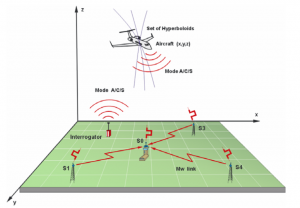
Figure 1 – TDOA principle of operation: The difference in arrival time of the signals are measured and used to calculate the differences in distance from each receiver. (ERA)
2.1.3 The detailed architecture of MLAT systems differ as different techniques of timing and synchronisation can be can be used by different systems. The basic system consists of interrogators that send an interrogation signal to the aircraft, receivers that receives the transponder signal from the aircraft, central processing architecture that processes the information and Air Traffic Services (ATS) display system.
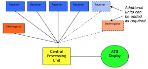
Figure 2 – Basic MLAT/Wide Area Multilateration (WAM) System Architecture
2.1.4 An MLAT system can have many receivers and interrogators. DFS in Germany is planning to install a system in Frankfurt with as many as 60 receivers. A signal must be received by a minimum of three receivers to be able to determine a position. However better accuracy will be achieved if the signal is received by more than three antennae.
2.1.5 MLAT systems can make use of the Mode A, C and S transponder signals as well as military Identification Friend or Foe (IFF), Automatic Dependent Surveillance – Broadcast (ADS-B) signals and transponder replies to Airborne Collision Avoidance System (ACAS) acquisition signals to calculate the aircraft’s position.
2.1.6 The MLAT system can be either passive or active. In a passive system the receivers will simply monitor incoming signals and will be dependent on the signals triggered by another source such as radar or generated automatically. In active systems the MLAT system will interrogate aircraft for a reply. The system can handle as many as 500 targets at a time.
2.1.7 Where very high accuracy of the aircraft’s position is required such as for height monitoring, each of the receivers can be paired with a GNSS clock to increase the accuracy of the time of receipt of the signal.
2.2 Benefits of MLAT
2.2.1 Coverage of MLAT systems can be tailored to meet requirements through careful placing of the receivers and the original system can be extended later by adding more receivers and interrogators if required.
2.2.2 MLAT systems have no moving parts and thus wear and tear is greatly reduced as a cause of failures of the equipment.
2.2.3 Acquisition and maintenance costs of MLAT systems are significantly less than that of conventional radar systems. The cost of the system depends on the coverage and the components in the system.
2.2.4 MLAT can achieve accuracy of 3 meters if required. This is achieved by increasing the number of receivers in the area where high accuracy is required.
2.2.5 No additional airborne equipment is required for an aircraft to be tracked by MLAT. The system uses normal transponder and ADS-B signals from the aircraft to determine the position of the aircraft.
2.2.6 The interference with surveillance by terrain can be reduced by careful placing of the antennae on or behind high terrain or structures to provide coverage behind the obstructions.
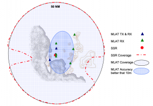
Figure 3 – Comparison of MLAT and SSR at Cape Town: At FL100 MLAT provides 100% coverage inside 50NM while SSR coverage is obscured by terrain. The accuracy of the SSR is 100 meters. (ATNS)
2.2.7 Receivers and interrogators are relatively small and can be easily installed on existing infrastructure.
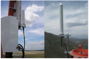
Figure 4 – Typical size of MLAT receiver (ATNS)
2.2.8 Additional receivers and interrogators added to the basic architecture provide redundancies that can maintain full operation and accuracy in the event of individual component failures. The failure of individual components such as receivers will only affect the system’s performance around the location of the failure and will not affect the entire area of coverage as would be the case with a component failure such as the antennae in a radar system.
2.2.9 Update rates of the position of aircraft are much higher than with radar as the updates can take place all the time and not only while the radar antenna is pointing towards the aircraft. Modern display systems can support update rates of 1 second.
2.2.10 The receivers are small and stationary, making it easy and cost effective to install in remote locations. Receivers have been installed successfully on off-shore platforms to extend the coverage of the MLAT system over water. The same coverage with radar would not have been cost effective, both due to the cost of providing the required platforms to house the radar antennae and the cost of the radar system.
2.2.11 One of the benefits of MLAT systems is that it can be incorporated into existing modern display systems as an additional surveillance input eliminating the need to update or replace the existing display system.
2.2.12 MLAT systems can make use of the Mode A, C and S transponder, IFF, ADS-B and ACAS signals to calculate the aircraft’s position.
2.3 Limitations of MLAT
2.3.1 The infrastructure is dispersed across the area of coverage and access to several remote sites may be required for maintenance. The security of the equipment at remote sites must be achieved to ensure reliability and integrity of the system.
2.3.2 MLAT cannot detect aircraft that are not equipped or that are not participating by sending the required signals for it to be detected. MLAT must therefore not be seen as similar in function to Primary Surveillance Radar, but rather as similar to SSR only.
2.3.3 The aircraft’s transponder can be a single point of failure for a single aircraft in the MLAT system.
2.4 Application of MLAT over wide areas
2.4.1 Where MLAT is used to cover a large area it is often referred to a Wide Area Multilateration (WAM). WAM can be deployed as a stand alone surveillance system or be incorporated with other surveillance systems as separate inputs into the same display system. Large areas such as a Terminal Area (TMA) or en-route sectors can be covered as required. Depending on the terrain and coverage, redundancy and accuracy required in the areas of operation the MLAT receivers and interrogators can be placed many miles apart throughout the area to be covered.
2.4.2 Combined systems with other new or existing surveillance and display technologies such as Mode S and ADS-B can be achieved as required. This combination with WAM is also known as Multistatic Dependent Surveillance (MDS). MDS allows seamless integration of all modes of transponders, ACAS and 1090 Extended Squitter and can be used for both ground surveillance and air surveillance. For example the MLAT system in Cape Town, South Africa makes use of 17 receivers that provide surveillance input to both a WAM system in the TMA as well as an A-SMGCS system at the airport.
2.4.3 WAM can be used to fill in gaps in existing surveillance coverage by incorporating an MLAT system or systems into the existing display system to cover the area not previously covered by the existing surveillance.
2.4.4 Where single surveillance systems are in operation redundancy and improvements in the integrity, availability and continuity of existing surveillance systems can be provided by incorporating a WAM system or systems with the same coverage as the existing surveillance system.
2.4.5 Due to the high accuracy of WAM it has been used successfully for monitoring aircraft flight paths for deviations and statistics as part of environmental monitoring programs.
2.5 Application of MLAT for surface surveillance
2.5.1 MLAT is also used successfully at many airports as a surveillance input in A-SMGCS. Due to the flexibility of the system allowed by the individual placing of the MLAT receivers between obstacles the system is very suitable for ground surveillance. Vehicles on the surface of the airport can be equipped with a small transponder device to make them visible to the MLAT surveillance.
2.5.2 MLAT can also support airport operations and management by providing real time position information about all aircraft and vehicles involved in the airport operations.
2.6 Application of MLAT for Height Monitoring
2.6.1 The height monitoring requirement for RVSM can be provided by MLAT. For RVSM a requirement exists for an accuracy of 25ft vertically and MLAT has demonstrated that it is able to meet this requirement. Accuracies of up to 10ft have been achieved with MLAT systems. Where such high accuracies are required each receiver is required to be synchronised with an independent GNSS clock. This height verification is not achieved through the use of Mode-C altitude information, but is calculated by the MLAT system.
2.7 Application of MLAT for precision approach monitoring
2.7.1 Where closely spaced parallel runways exist and where independent approaches are flown, certain requirements exist for the monitoring of aircraft on the approach to ensure they do not infringe on the No-Transgression Zone (NTZ) between the runways in order to ensure safety, also called Precision Runway Monitoring (PRM). This monitoring is normally done with the use of highly accurate radar systems (Short range radar (e-Scan radar) with a high update rate is used to provide accurate information in real time to controllers to allow immediate re-action in the event of a deviation from the approach path). Due to the cost of installing and maintaining these radars, limited use had been made of such radar systems. MLAT is sufficiently accurate to support this type of operation and is a cost effective alternative to these expensive specialised radar systems.
2.7.2 The Federal Aviation Administration (FAA) has done a comparative assessment between e-scan radar used for this purpose and MLAT and found that MLAT meets all the requirements and in some specification exceed that for the current radar systems.
2.8 Costs comparison between MLAT and SSR
2.8.1 Direct cost comparisons between SSR and MLAT are difficult to make as the coverage of systems in the same location will differ between MLAT and SSR radar. The exact cost of an MLAT system varies significantly depending on the configuration and requirements of the system and each case should be considered individually against the cost of a comparable SSR system. In most cases additional benefit such as improved coverage are present in the comparison that can not be measure in monetary terms.
2.9 Certification of MLAT systems
2.9.1 ICAO has not published specific technical standards for MLAT in ICAO Annex 10 Aeronautical Telecommunication and is not expected before 2011, however certification of MLAT systems is possible by combining existing specifications such as the existing Interrogation standards and radar surveillance standards as published on ICAO Annex 10 Aeronautical Telecommunications. A number of authorities throughout the world have followed this avenue and certification for MLAT has been achieved in countries throughout Asia, Europe, and North America. Several more countries are also in the process of working towards certification of MLAT using the same method.
2.10 SASP Development of MLAT Standards
2.10.1 ICAO SASP has agreed in May 2008 to publish 3 NM and 5 NM MLAT separation standards in PANS-ATM and this is not expected before 2011.
2.11 IFATCA Information on MLAT
2.11.1 IFATCA investigated MLAT in a working paper in 2002 (L022). This working paper centred on the basic functioning and basic architecture of the system. In recent years MLAT technology has matured and has found application in several specific objectives in ATM.
Conclusions
3.1 MLAT has been demonstrated to meet the accuracy, integrity, and reliability requirements for use as a surveillance system in civil aviation.
3.2 MLAT is comparable to SSR radar but at a much reduced cost, better reliability, and higher levels of accuracy than conventional SSR. MLAT is not a substitute for PSR.
3.3 Due to the flexibility of MLAT this technology is very versatile in its application and can serve in a multitude of ATS surveillance roles.
3.4 MLAT as a technology has matured in recent years to the level where it is fast becoming a common surveillance system in ATM.
Recommendations
It is recommended that;
4.1 This paper is accepted as information material.
References
Cancun 2002 – WP L022 Description of A ‘Multi-lateration’ Airport Ground System.
ERA: www.era.cz
IFATCA Report ICAO SASP 13th meeting of working group of the whole (WG/WHL/13) 12-23 May 2008, Montreal, Canada.
Multilateration Trials in Cape Town, ATNS OPSCOM, IP 66.
Multilateration Executive guide: www.multilateration.com
Roke Manor Research Limited: www.roke.co.uk
Safety Assessment Report Cape Town (APP & ACC) Provision of MLAT data into the existing air traffic system for ATS. ATNS.
Sensis: www.sensis.com
Wide Area Multilateration – Report on EATMP TRS 131/04 , NLR.

