
DISCLAIMER
The draft recommendations contained herein were preliminary drafts submitted for discussion purposes only and do not constitute final determinations. They have been subject to modification, substitution, or rejection and may not reflect the adopted positions of IFATCA. For the most current version of all official policies, including the identification of any documents that have been superseded or amended, please refer to the IFATCA Technical and Professional Manual (TPM).
50TH ANNUAL CONFERENCE, Amman, Jordan, 11-15 April 2011WP No. 93Study the Operation of Aircraft Flight Management SystemsPresented by TOC |
Summary
Aircraft Flight Management Systems are in place on almost all transport aircraft in use today. These systems have been developed in order to assist the operation of the aircraft and to improve safety. ATM considerations have generally been a by-product of FMS, rather than a primary aim, however such considerations are increasing in importance as the ATM system is changed to improve efficiency and reduce the impact of aviation on the environment.
Policy recommended by this paper is that FMS performance shall be harmonized with ATM system design.
Introduction
1.1 An aircraft Flight Management System is installed in an aircraft with the aim of improving efficiency and safety. Such system’s capabilities vary, but all have the fundamental task of reducing pilot workload by assisting with navigation and the management of aircraft systems. Any assistance that an FMS gives a pilot in achieving ATC requirements is often a by-product of its existence, rather than a main aim.
1.2 Some FMS manufacturers suggest that their equipment is already capable of providing all the support required for future 4D trajectory requirements and it is ATM systems that need updating to take advantage of this capability. Without a clear direction for future ATM systems, it is difficult to determine if the assertions of the FMS manufacturers are correct. What is certain is that many aircraft in operation today do not have the ability to fly existing procedures such as RNP/AR and Fixed Radius Transitions.
1.3 As the requirements of future ATM systems will require greater support from flight deck automation and the lead time for equipping aircraft is so long, it is important that ATS communicates such requirements to aircraft manufacturers without delay. Standards for FMS should be developed which include ATC considerations.
Discussion
2.1 General
2.1.1 The concept of an aircraft Flight Management System (FMS) has existed for many years, with the first digital systems delivered in the early 1980s on aircraft such as the Boeing 767 and Airbus A310. FMS of varying capability can be found today on aircraft ranging from light aircraft through turbo-props to the most sophisticated on modern airliners. There are several FMS manufacturers and for large aircraft, there will generally be two or more FMS options available at the time of manufacture. An FMS automates a wide variety of in-flight tasks and can consist of many components; however there is a set of features common to most systems:
- A Flight Management Computer (FMC)
- A Flight Control System (FCS)
- An Aircraft Navigation System
- An Electronic Flight Instrument System (EFIS) or equivalent conventional instrumentation
2.1.2 Fundamental to an FMS is the navigation database which contains details of the aerodromes, routes, SIDs, STARs, approaches and so on that could potentially be used on the flight. The pilot either builds a flight plan from the navigation database or downlinks the plan before departure.
2.1.3 The main task of an FMS is performed by the Aircraft Navigation System which manages an aircraft’s progress throughout the flight, tracking its position relative to the route and providing guidance to the pilots and auto-pilot as to the track to be followed and climb and descent profiles. The FMS determines its position using whatever inputs are provided on the aircraft; these include technologies such as GPS, Inertial Navigation Systems and traditional radio navigation aids.
2.1.4 Most modern commercial and business aircraft are equipped with EFIS, which replaces conventional instrumentation. The track to fly is displayed on a Navigation Display situated close to the primary flight display. The pilot interacts with the FMS through the display and keypad found on a device usually known as the Multifunction Control Display Unit (MCDU). As many controllers have experienced when operator fleets change from conventional control to FMS, pilots now spend a greater part of their time “heads down” entering data into the MCDU. In order to reduce the impact of this most operators have procedures which disallow long and complex interaction with the FMS when flying below certain altitudes; such procedures can leave ATS with the view that aircraft are not as flexible now as in the past.
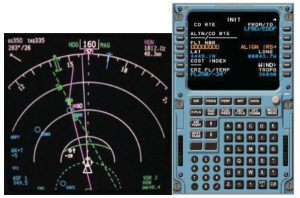
Navigation Display and Multifunction Control Display Unit
2.1.5 The FCS receives sensor information from other aircraft systems to control the Autopilot and the Flight Director, which is displayed on the Attitude Indicator on the Primary Flight Display to provide lateral and vertical guidance to the pilot.
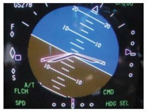
Attitude Indicator showing a bank to the left as guided by the Flight Director
2.1.6 ATM systems can provide a limited ability for ATS to interact with the FMS on some aircraft. Examples of this interaction include:
- Sending and receiving Datalink messages
- The establishment of ADS/C contracts
- The receipt of mode S enhanced surveillance data from suitably equipped aircraft
The future promises greater interaction between an ATM system and aircraft FMS through the exchange of 4D trajectories and similar tasks.
2.2 IFATCA
2.2.1 At the 2008 IFATCA conference in Arusha, TOC presented a working paper entitled “Investigate 4D Trajectory Concepts “ (working paper 86). In that paper it was concluded that most FMS do not regard ATC requirements as “hard requirements.” Since 4D trajectory contracts require aircraft to comply with negotiated contracts, this issue must be solved. Accordingly, provisional policy was adopted.
2.2.2 IFATCA provisional policy is [AAS 1.9]:
| “The flight management system shall accept ATC requirements as compulsory requirements. Airspace must be designed to support 4D trajectory management.” |
2.2.3 In order to meet requirements such as crossing heights at a point, the FMS often cannot operate on its own. For example, the use of speed brakes requires pilot action; the FMS may prompt the pilot to do this, but it would not be considered good practice for the FMS to automatically deploy speed brakes.
2.3 Tracking at waypoints
2.3.1 Associated with this paper is agenda item B.5.6, ‘Produce definitions of “fly-by” and “flyover”’, which examines fly-by and flyover waypoints and which also looks at fixed radius turns and transitions. As agenda item B.5.6 concludes, turns at fly-by and flyover waypoints are neither predictable nor repeatable and the actual track flown varies according to the magnitude of the track change, aircraft ground speed, altitude and bank angle.
2.3.2 Many FMS have a pilot or operator selectable bank factor setting which permits the crew to establish how steep the bank angle will be and therefore how aggressively the aircraft will turn. It is the highest bank angle to be used by the FMS except when flying a SID, a STAR, an approach or when holding. For low settings (such as 5°), the FMS will anticipate course changes further in advance and make shallower turns. For higher values, the turn is initiated closer to the actual turn point and the bank angle is steeper. When flying a SID, STAR or approach the FMS will automatically use a higher angle of bank if required, in the order of 20°.
2.3.3 ICAO Doc 8168 Procedures for Air Navigation Services, Volume 2 Construction of Visual and Instrument Flight Procedures (PANS-OPS), Part III – Section 2, Chapter 1:
1.4.1 Flyover waypoint
1.4.1.1 Components of the flyover turn. A flyover turn is broken down into the following components for the purpose of calculating the minimum stabilization distance:
a) an initial roll-in at the flyover point; followed by
b) a straight 30° intercept course with the next leg;
c) a roll-out at the new course; and
d) a 10-second delay to account for bank establishing time.
2.3.4 ICAO PANS-OPS assumes a 30° intercept course at a flyover waypoint. However following pilot reports of unexpected behaviour in flight, an Airbus A320 simulator was flown through a 120° track change after a flyover waypoint at the end of a SID. In this case, the FMS commanded a 45° intercept, for reasons that are not yet understood. The transition area defined in Eurocae/RTCA document ED-75B/DO-236B, “MASPS Required Navigation Performance for Area Navigation” as described in agenda item B.5.7 is sufficiently large to not require such a sharp intercept. As the aircraft took up a 165° change in heading during the manoeuvre there was the potential for a loss of separation against following traffic tracking to the waypoint.
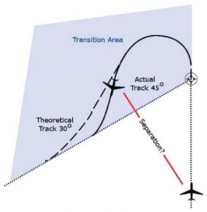
Transition area at a flyover waypoint
2.3.5 ATC can take steps to prevent separation being infringed in this circumstance; however the best solution is to ensure that procedures are harmonized with aircraft capability to increase the predictability of the trajectory.
2.3.6 Where two waypoints are close to each other, a procedure designer will take account of aircraft speeds to ensure that there is sufficient distance between the two waypoints to allow the aircraft to stabilise after passing the first before taking up a turn at the second. An example of this is in the following illustration.
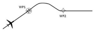
Through speed mismanagement by the pilot or by controller action it is possible for the aircraft to not have sufficient distance to stabilise after the first waypoint before it is necessary to commence manoeuvring at the second waypoint. An example of controller action, which could cause this is to issue a clearance direct to the first waypoint which makes the first turn even sharper such as the blue dashed track in the following illustration.
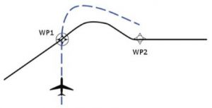
In simulating this, the A320 used in researching this paper flew the path indicated by the dashed line until abeam WP2 and then continued on the same heading to intercept the track from WP2. It is unlikely that all FMS will handle this situation in the same way and it has been suggested that some FMS will order an initial left-hand turn after crossing WP1 to give sufficient room to stabilise before WP2. While no definite examples have been given to support this suggestion, this could be very undesirable situation from the point of view of ATS.
2.4 Tracking between waypoints
2.4.1 When using radio navigation aids such as a VOR, an IFR aircraft flies a specified track from the aid or a specified track to the aid. An FMS will allow a pilot to intercept a specified track to and from a waypoint where this coincides with a radio navigation aid, however the normal procedure is to fly the great circle track from one waypoint to the next. Some FMS do allow a waypoint to be designated as a pseudo VOR for the purposes of tracking, but operationally these are not used.
2.4.2 When tracking between waypoints, the FMS will typically show the previous waypoint as the “From” point and the next waypoint as the “To” point. The distance displayed is however always the distance to the next waypoint.
2.4.3 Many ATC separations are based on aircraft being established on the nominal centre-line of an airway. In applying lateral separations, a procedural controller will typically ask the pilot of an aircraft outbound from a VOR to report established on the outbound radial. This however may not be enough; with FMS treating all waypoints as fly-by by default, it is perhaps also necessary to ensure that a potentially conflicting aircraft inbound to the VOR is still established on the inbound radial. As has been noted in agenda item B.5.6, aircraft can commence a turn as much as 20 nautical miles before a fly-by waypoint.
2.4.4 In November 2010, a paper proposing VOR like GNSS separations was presented to the ICAO Separation and Airspace Safety Panel (SASP). In this paper and its appendix (proposed ICAO circular 322) the point is made that “The separation specified in this section shall not be applied while the aircraft is turning.”.
2.4.5 Central to some horizontal separations is the concept of an aircraft being established on the centreline of a track. It is critical that the flight displays can indicate to the pilot when the aircraft is not established on track. All three FMS that have been examined in the research for this paper do indeed indicate to the pilot that the aircraft is off track whilst in the turn. The exception would be for a fixed radius transition – an aircraft flying one of these is by definition still on track even though the aircraft is turning.
2.4.6 The FMS displays the distance to a waypoint as if this is at the same altitude as the aircraft. As should be well understood, a DME distance is however the slant range distance to the DME. ICAO Doc 4444 Procedures for Air Navigation Services – Air Traffic Management (PANS-ATM) does provide for the two methods of determining distance with applicable separations and phraseologies, with no differentiation made between a DME distance from a DME station and a GNSS distance from a co-located waypoint in applying longitudinal separations. Nevertheless, a controller should be aware that the actual spacing between two aircraft where a GNSS equipped aircraft is closer than a DME equipped aircraft to the reference DME facility or waypoint can be considerably less than two like equipped aircraft.
2.4.7 A controller operating in a procedural environment could gain an incorrect mental picture of the traffic when using a combination of DME and GNSS derived distance reports. When two differently equipped aircraft are reporting the same distance, the DME equipped aircraft will always be closer to the DME station than the GNSS aircraft is to the co-located waypoint. This is particularly important when the DME aircraft is at high altitude close in to the DME station.
2.5 Flight ID
2.5.1 At the 2010 IFATCA conference in Punta Cana, TOC presented a working paper entitled “Study Issues Associated with Incorrect Flight Identification“ (working paper 83). In that paper it was concluded that “… often pilots cannot change the Flight ID once airborne”.
2.5.2 On FMS equipped aircraft, Flight ID is entered via the MCDU. All FMS examined when researching this paper do now allow the amendment of Flight ID. However, on some FMS this facility has only been provided by recent software updates and it is likely that many FMS do still prevent such amendments. Even if an amendment via the MCDU is possible, some FMS require a software update to permit a change of the Flight ID that is actually transmitted. The Flight ID reported in electronic position reports is usually the same ID the aircraft used when first airborne.
2.6 Time Source
2.6.1 Many older FMS equipped aircraft are not equipped with GNSS. On such aircraft it is thus not surprising that the source of time for the FMS time is a manual update by the crew. What is surprising is that some aircraft equipped with GNSS integrated into the FMS either do not use GNSS as a source of time for the FMS or will reduce the precision to the nearest minute. Accordingly, the aircraft time may not be as accurate as ATS requires; this could become an issue in the future when ATS required times of arrival get to a precision of less than 30 seconds.
2.7 Cost Index
2.7.1 Most FMS on transport aircraft are able to maintain aircraft performance to meet a required “Cost Index”. An aircraft Cost Index is a measure of the cost of fuel in proportion to all other operational costs. A general interpretation of Cost Index is that the lower its value, the more “importance” the FMS places on saving fuel.
2.7.2 Selecting a low cost index may result in a lower climb rate, lower climb and cruise speeds, a higher cruise altitude, later descent and a slower descent speed in order to minimise fuel burn. A high Cost Index will be selected in order to minimise time in the air, that is to reduce non-fuel costs and will therefore result in higher speeds.
2.7.3 There is great variation between operators as to the Cost Index used for a given aircraft type or in a given situation; the Cost Index can even vary between flights by the same operator. ATC cannot assume that all aircraft of the same type will perform in the same fashion during any given phase of flight and speed control or assigned climb/descent rates may be necessary to achieve the desired result.
2.8 Navigation Database Accuracy
2.8.1 It has always been vital to ensure that navigation data held on board aircraft is correct at all times. In general terms a pilot could examine the coding for a procedure and compare that with what is published in the AIP. However as the AIP may not necessarily contain all the information about some procedures such as the centre and radius of a Radius to Fix turn in RNP Approval Required approaches, such a comparison is now not always possible and as such approaches can be located in areas with no ground based NAVAIDS, the integrity of the navigation database has become absolutely critical.
2.8.2 The IFALPA ATS committee has considered the regulatory requirements and the processes that should be in place to ensure Navigation Database accuracy. In a paper to be presented to the IFALPA conference in the week prior to the IFATCA conference the IFALPA proposes draft policy. From IFALPA paper 11ATS014:
3. Ensuring and Maintaining NavData Integrity
In operational terms, there are two processes that should be in place to ensure Navigation Database accuracy and reliability:
1. Initial Procedure Validation
Operators are required to validate every RNP procedure before flying the procedure in IMC to ensure the flyability of the procedure in their aircraft. This is generally done by flying the procedure in the simulator representing the aircraft that the procedure will be flown in. It can also be done in the aircraft in VMC (Visual Meteorological Conditions).
The depicted procedure on the map display must be compared to the published procedure. The entire procedure must be flown to ensure the path is flyable, does not have any lateral or vertical path disconnects, and is consistent with the published procedure. Generally, navigation data for a given procedure are obtained from a state source.
2. Ongoing Navigation Database Integrity
As a part of RNP SAAAR operational approval, each operator shall develop (if they haven’t already) a Nav Data Integrity Program. This program consists of a process that verifies the continued accuracy of the FMC Navigation Database. This is done by establishing that an initial Navigation Database is correct (a truth table) and then monitoring and verifying any and all changes made to that Navigation Database with each normal update. Changes are evaluated utilizing chart data and simulators as necessary.
For RNP Approaches, SIDs, and STARs; all waypoints, navaids, headings, speeds, altitudes and glide paths shall be checked. The goal is to make sure that any changes made do not impact the flyability or the integrity of the approach.
If there are minor discrepancies found that do not significantly affect the flyability of the approach and can be safely handled by the crew and that require crew notification, then they shall be notified. If a discrepancy is found that will prevent the use of the approach and a new, correct Navigation Database cannot be issued, the affected RNP procedure will be put out of service for that data cycle and crews notified.
While it is not required that a pilot accomplish the entire process, it is highly recommended that a pilot with both operational knowledge of both the RNP AR procedures involved and the database integrity procedures involved oversee the process.
2.9 Navigation Database Procedure Identification
2.9.1 SIDs and STARs are often identified by a seven character name, comprising the name of a waypoint at the end of the procedure for a SID or the start of the procedure for a STAR, a “version number” and a character e.g. A or B to indicate which variant of the procedure applies.
2.9.2 The format of data stored in an aircraft’s Navigation Database is defined by the ARINC 424 standard. In this standard, SID or STAR identification is restricted to 6 characters; moreover some FMS are only capable of 5 character identification. ARINC 424 does detail how to convert a 7 character procedure identifier into 5 or 6 characters for the database.
2.9.3 There have been many cases where the pilot has selected an incorrect procedure, in some cases possibly because the FMS identifier does not match the AIP procedure name. It would seem logical that the FMS identifier used in an FMS should exactly match the AIP, but regardless it is for the present time incumbent upon procedure designers to ensure that the abbreviated name of a particular procedure cannot be confused with another similarly named procedure for the same geographic area.
2.10 Required Time of Arrival
2.10.1 As ATC systems evolve, there will be a greater reliance on aircraft meeting a Required Time of Arrival (RTA) or required times over a point. In order to achieve improved or even present capacity the precision needed for such times could be ten seconds or less.
2.10.2 While many FMS do support the concept of RTA, currently the precision of these vary, with the best reportedly to a precision of +/-6 seconds, many FMS however can only achieve a precision of one minute. Moreover, some FMS do not provide RTA support to the pilot when the aircraft is in climb or descent.
2.11 Variation between FMS Capability
2.11.1 It is not unexpected that new features are often only available on new aircraft or those that receive an FMS upgrade. For example the ability to fly a Fixed Radius Transition (FRT) has only recently become available for some A320 FMS. In the meantime ATS is developing new requirements through programs such as SESAR and NEXTGEN.
2.11.2 As the expected life of an aircraft is 20 years or more and the cost of retro-fitting systems is very expensive, ATS needs to signal future requirements long before these become operational. Failure to do this will delay the introduction of procedures and ATS system enhancements and increase the time during which mixed mode operation will be required. For example, a barrier to the implementation of FRT is a lack of aircraft capable of flying such a transition.
2.11.3 Just as performance standards for navigation, surveillance and communication are or will be defined for a particular airspace; consideration should be made to define performance standards for an aircraft to meet ATC requirements such as Required Time of Arrival and altitude requirements. In other words an aircraft should be required to comply with a trajectory assigned by ATC within a defined performance standard.
2.12 The Future
2.12.1 Of immediate concern for ATS is an aircraft’s ability to carry out operations in today’s environment. This paper has highlighted that aircraft capability is preventing the implementation of procedures such as RNP/AR and FRT in many airspaces today. If aircraft are not equipped to meet the relatively simple needs of RNP today, how can it be expected that they will meet the more complex requirements of tomorrow?
2.12.2 While the concept of 4D trajectory exchange between an aircraft and an ATM system is in use in small areas such as parts of Sweden, it is not certain that the system as implemented will be suitable for general use. It needs to be proven that trajectories can be modelled and executed to the precision required to maintain throughput in such a system. Standards for 4D FMS are still being developed; further study should be made of these standards and existing implementations of 4D FMS.
Conclusions
3.1 FMS design does not necessarily incorporate the requirements of the ATM system.
3.2 ATM procedures and aircraft trajectories can be inconsistent. The solution is to ensure that ATM procedures and aircraft capability are harmonized to ensure the predictability of the trajectory.
3.3 In isolation existing provisional policy does not fully resolve the inconsistency highlighted in conclusion 3.2.
3.4 FMS processing of time sources may not be accurate enough to meet future ATM requirements.
3.5 The capability of FMS vary greatly between aircraft, however a performance standard for FMS should be considered for designated airspace to allow pilots to meet ATS requirements.
Recommendations
It is recommended that;
4.1 IFATCA provisional policy:
The flight management system shall accept ATC requirements as compulsory requirements.
on page 3 2 1 15 of the IFATCA Technical and Professional Manual is deleted.
4.2 IFATCA policy is:
The flight management system shall accept ATC requirements as compulsory requirements.
and is included in the IFATCA Technical and Professional Manual.
4.2 IFATCA policy is:
FMS performance shall be harmonized with ATM system design.
and is included in the IFATCA Technical and Professional Manual.

