
DISCLAIMER
The draft recommendations contained herein were preliminary drafts submitted for discussion purposes only and do not constitute final determinations. They have been subject to modification, substitution, or rejection and may not reflect the adopted positions of IFATCA. For the most current version of all official policies, including the identification of any documents that have been superseded or amended, please refer to the IFATCA Technical and Professional Manual (TPM).
50TH ANNUAL CONFERENCE, Amman, Jordan, 11-15 April 2011WP No. 92Produce Definitions of “Fly-by” and “Fly-over”Presented by TOC |
Summary
The concept of “fly-by” and “flyover” waypoints is integral to RNAV and as such has been in existence for quite some time. As Performance Based Navigation is being increasingly used to reduce the distances between routes to a minimum, air traffic controllers have been surprised to see that aircraft do not follow consistent paths when turning from one track to another. This issue has been documented by Eurocontrol, ICAO and others. Such surprises should be prevented by changes in route structure and controller training.
More recent innovations such as the fixed radius transition for the en-route environment should allow for predictable flight paths and ensure separation where close spacing between routes or between a route and terrain or a danger area is desired.
This paper proposes policy to improve the understanding of fly-by turns and also policy to encourage the use of the fixed radius transition where predictability of aircraft tracking is required in the turn.
Introduction
1.1 The terms “fly-by waypoint” and “flyover waypoint” are well known by pilots, Flight Management System (FMS) manufacturers and procedure designers. Air Traffic Controllers may however only have a general understanding of the terms gained through observing aircraft operations or through re-conceived ideas.
1.2 This paper examines the ICAO definitions for “fly-by” and “flyover” and explains how the two waypoints are used. It also introduces the Radius to Fix (RF) turn as used in some RNP/AR (Approval Required) approaches and the Fixed Radius Transition (FRT) that is available in the enroute environment, both of which ensure the aircraft track is contained whilst turning from one track to another.
1.3 The paper is related to agenda item B.5.7, “Study the operation of aircraft Flight Management Systems”, which includes a study of how FMS equipped aircraft handle fly-by and flyover waypoints.
Discussion
2.1 ICAO
2.1.1 ICAO Doc 8168 Procedures for Air Navigation Services, Volume 2 Construction of Visual and Instrument Flight Procedures (PANS-OPS), Chapter 1 – Definitions:
“Waypoint. A specified geographical location used to define an area navigation route or the flight path of an aircraft employing area navigation. Waypoints are identified as either:
Fly-by waypoint. A waypoint which requires turn anticipation to allow tangential interception of the next segment of a route or procedure, or
Flyover waypoint. A waypoint at which a turn is initiated in order to join the next segment of a route or procedure.”
2.1.2 The following diagram is Figure III-2-1-1 from volume 2 of ICAO PANS-OPS. This illustrates the difference between the two types of waypoint. The diagram emphasises that for the same change in track, at a flyover waypoint an aircraft flies a greater distance whilst manoeuvring onto the new track.
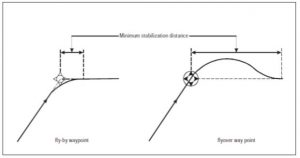
2.1.3 The manoeuvre undertaken at a fly-by waypoint is a simple turn with a constant angle of bank. At a flyover waypoint, the manoeuvre is more complicated and consists of:
a) an initial roll-in at the flyover point; followed by;
b) a straight 30° intercept course with the next leg;
c) a roll-out at the new course.
The “straight 30° intercept course” is investigated further in working paper “Study the operation of aircraft Flight Management Systems” as it has been found that in certain circumstances an FMS will intercept at a much greater angle.
2.1.4 For both turns, the track the aircraft follows whilst manoeuvring from one track to another is referred to as a transition.
2.2 Fly-by Transition
2.2.1 Eurocae/RTCA document ED-75B/DO-236B, “MASPS Required Navigation Performance for Area Navigation” contains requirements for navigation systems operating in an RNP environment. On fly-by transitions, paragraph 3.2.5.4 says:
For fly-by transitions, no predictable and repeatable path is specified, because the optimum path varies with airspeed and bank angle. Instead, predictable and repeatable boundaries of the transition area are defined below for these types of transitions.
It then continues:
Fly-by transitions shall be the default transition when the transition type is not specified.
The theoretical transition area requirements for fly-by transitions which follow in this section are only applicable if the following assumptions are followed:
- course changes do not exceed 120 degrees for Low Altitude transitions; and
- course changes do not exceed 70 degrees for High Altitude transitions.
The definition of High Altitude and Low Altitude in this section is above and below FL195. When passing through FL 195 during a fly-by transition, the high altitude values may be applied for determining the theoretical boundaries throughout the transition.
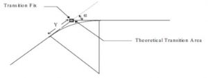
2.2.2 While no predictable and repeatable path is specified, ED75B/DO-236B does provide a methodology for determining the boundaries of the transition area. The parameters which influence the transition area are:
- the track change angle
- the aircraft’s ground speed
- the aircraft’s altitude
- the bank angle taken up by the aircraft
2.2.3 At its November 2010 meeting, the ICAO Separation and Airspace Safety Panel (SASP) accepted working paper 20 “Fly-by Turns”, presented by the IFATCA representative to SASP. The purpose of this paper was to consider the effect of fly-by turns on lateral separation. The paper used the Eurocae/RTCA methodology to calculate tables of theoretical transition areas, which follow.
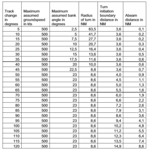
Low Altitude Transitions
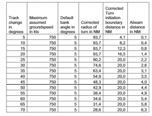
High Altitude Transitions
Note: The corrected radius of turn and corrected turn initiation boundary distance are the result of limiting the initiation of the turn at 20NM.
2.2.4 The fly-by transition areas defined here are significantly larger than that required for acceptable transition performance. This is a result of accommodating near worst-case conditions of ground speed and roll angle. As can be seen from the tables, at low altitude in the worst case a turn is initiated 14.9 nm before the fly-by waypoint and at high altitude at 20 nm.
2.3 Flyover Transition
2.3.1 Eurocae/RTCA document ED-75B/DO-236B, “MASPS Required Navigation Performance for Area Navigation” defines a trapezoidal shaped theoretical transition area for a flyover waypoint in paragraph D.5.4.2.
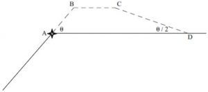
EXAMPLE OF FLY-OVER TRANSITION AREA (LOW ALTITUDE ONLY)
2.3.2 The mathematics used to determine the locations of points A to D is contained in the document, but are beyond the scope of this paper. However, in order to compare flyover transitions with flyby, TOC calculated the positions of points A, B C & D for a specific example.
2.4 Transition Comparison
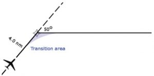
2.4.1 A comparison of fly-by and flyover transitions is best illustrated graphically with two scale drawings of the same track change. The following figure shows the theoretical worst case low level fly-by transition with a 50° track change. The transition area commences 4.0 nm prior to the fly-by waypoint and extends to a maximum of 0.9 nm away when abeam the waypoint.
The following figure shows the theoretical worst case low level flyover transition for the same track change. The trapezoidal transition area extends to 3.84 nm away from the new track and 19.3 nm along the new track.
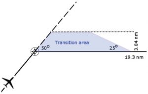
2.4.2 As can be seen, the transition area for a flyover waypoint can be much larger than that for a fly-by waypoint. Nevertheless, it should be noted that fly-by transitions at high altitudes can still be large, in some cases extending to 20.0 nm before and after the waypoint and the abeam position could be as much as 6.3 nm away from the waypoint.
2.4.3 Fly-by waypoints have three major advantages over flyover waypoints.
1. The transition from one track to the other is a shorter distance.
2. The transition from one track to the other is smoother as there is only one turn made.
3. The theoretical transition area is smaller.
2.4.4 As they are more efficient, fly-by waypoints are used almost exclusively in preference to flyover waypoints. Flyover waypoints are normally only used to ensure that an aircraft passes over a specific point such as at a Missed Approach Point or where protection from terrain or airspace is required. However the path followed during the turn at either waypoint is neither predictable nor repeatable; as we have seen this varies according to the difference in angle between the tracks, aircraft ground speed and bank angle. This point is reinforced by ICAO.
2.4.5 ICAO Doc 9613 Performance-based Navigation (PBN) Manual Volume 1, 3.5.4:
Air traffic controllers sometimes assume that, where all aircraft operating in an airspace may be required to be approved at the same level of performance, these aircraft will systematically provide entirely or exactly repeatable and predictable track-keeping performance. This is not an accurate assumption because the different algorithms used in different FMS and the different ways of coding data used in the navigation database can affect the way an aircraft performs during turns. Exceptions are where radius to fix (RF) leg types and/or fixed-radius transitions (FRT) are used. Experience gained in States that have already implemented RNAV and RNP shows that such mistaken assumptions can be corrected by adequate training in performance-based navigation. ATC training in RNAV and RNP applications is essential before implementation so as to enhance controllers’ understanding and confidence, and to gain ATC “buy-in”. PBN implementation without adequate emphasis on controller training can have a serious impact on any RNP or RNAV project schedule (see the Controller Training paragraphs in each navigation specification in Volume II of this manual, Parts B and C).
2.5 ATM View
2.5.1 Without referring to PANS OPS or the ICAO PBN manual, an Air Traffic Controller might reasonably consider a “flyover waypoint” to be a point that is treated by a pilot in a manner similar to conventional tracking using radio navigation aids such as NDBs and VORs; that is aircraft “overhead” the aid and then manoeuvre to join the new track required.
2.5.2 Such an interpretation does match the actual practise for flyover waypoints. As such the ICAO definition for flyover waypoint is compatible with the ATM viewpoint.
2.5.3 The term “fly-by waypoint” is not necessarily so easily interpreted by an Air Traffic Controller. As a group we might reasonably consider this to mean that the aircraft does not “overhead” the waypoint and instead passes by it. Without education we would probably differ in our understanding of:
- how close the aircraft does in fact get to the waypoint
- how soon before the waypoint the aircraft will commence its turn and
- how far beyond the waypoint the aircraft will complete the turn
ICAO thus recommends training for controllers providing a service in airspace subject to Performance Based Navigation; an example of this follows.
2.5.4 ICAO Doc 9613 Performance-based Navigation (PBN) Manual Volume 2, Part B 3.2.6 Controller training:
Air traffic controllers who provide RNAV terminal and approach control services in airspace where RNAV 1 and RNAV 2 is implemented, should have completed training that covers the items listed below:
3.2.6.1 Core training
a) How area navigation systems work (in the context of this navigation specification):
i) include functional capabilities and limitations of this navigation specification;
ii) accuracy, integrity, availability and continuity;
iii) GPS receiver, RAIM, FDE, and integrity alerts;
iv) waypoint fly-by versus fly-over concept (and differences in turn performance).
2.5.5 Even where Air Traffic Control is providing a radar control service we may not appreciate how it is that aircraft are going about changing track unless we observe the manoeuvres closely. To illustrate this, the graphic below shows the nominal track to and from a point in the dashed black line and the actual track flown by a B733 cruising at F360 in solid blue. The aircraft commenced the turn for the 21° course change 3nm prior to the waypoint and completed the turn 3nm after the waypoint. In order to observe the difference between the nominal track and the actual track flown, it was necessary to have the radar display set to a very short range.

From the tables presented in paragraph 2.2.3 however, the aircraft could have commenced the turn up to 16.8 nm miles before the waypoint and passed up to 1.4 nm abeam the waypoint.
2.5.6 Such a wide variation between tracks taken by aircraft making turns at waypoints can surprise controllers. When this is taken into account by procedure designers and airspace planners and with adequate controller training as recommended by the PBN manual, this should not be an issue. SASP working paper 20 recommends that the tables presented in 2.2.3 be published in ICAO PANS-ATM, so that airspace planners and air traffic controllers can take the effect of turns into account in the separation of aircraft.
2.5.7 Another aspect which may come as a surprise to Air Traffic Controllers is that radio navigation aids are treated by an FMS as fly-by waypoints unless these are depicted as flyover in a procedure, for example where passing over the navigation aid denotes the Missed Approach Point.
2.5.8 A potential issue may arise with the introduction of conformance monitoring by the ATM system. The unpredictable nature of aircraft tracks at fly-by and flyover waypoints may lead to incorrect conformance alerts or alternatively conformance issues not being highlighted in a timely manner.
2.5.9 PBN does provide two fixed radius paths (FRP) that may resolve the turn predictability issue. These are the Radius to Fix (RF) turn as used in some RNP/AR approaches and the Fixed Radius Transition (FRT) that is available in the en-route environment. Both of these ensure that within the limits of the required navigation performance, the aircraft is contained on a pre-defined track whilst turning from one track to another and are documented in simple terms in the PBN manual.
2.5.10 ICAO Doc 9613 Performance-based Navigation (PBN) Manual Volume 1, 5.2 Fixed radius paths:
5.2.1 Fixed radius paths (FRP): The FRPs take two forms: one is the radius to fix (RF) leg type (see Figure I-A-A1-4). The RF leg is one of the leg types described that should be used when there is a requirement for a specific curved path radius in a terminal or approach procedure. The RF leg is defined by radius, arc length, and fix. RNP systems supporting this leg type provide the same ability to conform to the track-keeping accuracy during the turn as in the straight line segments.
Note.— Bank angle limits for different aircraft types and winds aloft are taken into account in procedure design.
Figure I-A-A1-4. RF leg
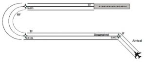
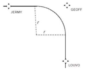
5.2.2 The other form of the FRP is intended to be used with en-route procedures. Due to the technicalities of how the procedure data are defined, it falls upon the RNP system to create the fixed radius turn (also called a fixed radius transition or FRT) between two route segments (see Figure I-A-A1-5).
5.2.3 These turns have two possible radii, 22.5 NM for high altitude routes (above FL 195) and 15 NM for low altitude routes. Using such path elements in an RNAV ATS route enables improvement in airspace usage through closely spaced parallel routes.
2.5.11 Both types of fixed radius turns are presently supported by only a few aircraft and FMS combinations. For an RNP/AR approach, this is not a problem as specific authorisation is required from a regulator before such an approach is available for use by a particular aircraft and crew. If we are to see the benefit of fixed radius transitions in the en-route environment, which might then allow more closely spaced routes, a greater number of aircraft will need the capability of flying the transitions.
Conclusions
3.1 ICAO definitions for “fly-by waypoint” and “flyover waypoint” are adequate.
3.2 Training in accordance with ICAO provisions is necessary to ensure that controller understanding of such terms is consistent with the ICAO definitions.
3.3 Understanding of the fly-by concept could be improved by publishing tables in PANS-ATM which show the maximum dimensions of fly-by transitions.
3.4 Fly-by waypoints lead to more efficient aircraft operation and so they are the preferred option where it is not imperative that an aircraft crosses over a waypoint.
3.5 Turns at fly-by and flyover waypoints are neither systematically predictable nor repeatable and the actual track flown can widely vary between aircraft.
3.6 PBN does provide mechanisms for predictable tracks in the turn, however at present few aircraft have the capability to fly these in the en-route environment.
Recommendations
It is recommended that;
4.1 IFATCA policy is:
Tables, which show the maximum dimensions of fly-by transitions, should be published in ICAO PANS-ATM.
and is included in the IFATCA Technical and Professional Manual.
4.2 IFATCA policy is:
Where predictability in the turn is required, PBN fixed radius path mechanisms should be implemented.
and is included in the IFATCA Technical and Professional Manual.

